

♦SENSORLESS VECTOR, CLV and permanent magnet synchronous motor control PMSM
♦Intelligent AUTOTUNING functions for easy setup
♦Compact in size, modular in concept, rugged construction, build for the worldwide market
♦Flexible inverter control, dual high resolution analogue inputs, free mapping for all I/O channels
♦Ready for all commonly used fieldbus systems
♦Universal parameter-set for all kind of industrial and residential applications, including integrated
♦PID/ controller routines
♦Smart PC-tools for inverter control, parametrization and troubleshooting
♦Parameter-duplication stick
♦EMC fi lter(C3 class) integrated.optional C1 footprint fi lter.
♦Approved and certified for worldwide standards, by independent bodies.
E2100 Series inverters
The newest generation of inverters : general purpose, for wide range applications, from the simpliest speed control to the most complex process automation system. Modular concept, easy configurable,a lot of different setup parameters make this inverter series suitable for the high volume OEM-marketsingle applications as well. Assembled on modern high speed lines, using high quality components from first class vendors. This is the guarantee for cost efficiency, reliabilityabsolute quality. Green production: through environmentally friendly operating processes, a must, for a product which final destination is protecting the environment by saving energyresources. All products are compliant with international standards.CE,UL individual approvals, performedcertified by independent bodies, give the customer the trust in a world class product.
Technical product data
| Items | Contents | |
| Input | Rated Voltage Range | 3-phase 380-480V (+10%, -15%) note 1 |
| 3-phase 220V~240V ±15% | ||
| 1-phase 220-240V ±15% | ||
| Rated Frequency | 50/60Hz | |
| Output | Rated Voltage Range | 3-phase 0-INPUT (V) |
| Frequency Range | 0.50 590.0Hz (In SVC control mode, the max frequency should be lower than 500Hz.) | |
| Control Mode | Carrier Frequency | 800 16000Hz; Fixed carrier-wave and random carrier-wave can be selected by F159. |
| Input Frequency Resolution | Digital setting: 0.01Hz, analog setting: max frequency X 0.1% | |
| Control Mode | For induction motor: | |
| SVC (open-loop vector control) control, V/F control | ||
| VC (Closed-loop vector control) control | ||
| For PMSM: SVC (open-loop vector control) control | ||
| Start Torque | 0.5 Hz / 150% (SVC) 0Hz/180% (VC),5% of rated speed/100% of rated torque (PMSM SVC) | |
| Speed-control Scope | 1:100 (SVC), 1:1000 (VC), 1:20 (in PMSM SVC) | |
| Steady Speed Precision | ±0.5% SVC), ±0.02%(VC) | |
| Torque Control Precision | ±5% | |
| Overload Capacity | 150% rated current, 60 seconds. | |
| Torque Elevating | Auto torque promotion, Manual Torque Promotion includes 1-20 curves. | |
| V/F Curve | 3 kinds of modes: beeline type, square type and under-defined V/F curve | |
| Startup mode | Direct startup, speed track startup (V/F control) | |
| DC Braking | DC braking frequency: 0.20-50.00 Hz,braking time: 0.00~30.00s | |
| Jogging Control | Jogging frequency range: min frequency~ max frequency, jogging acceleration/decelerationtime: 0.1~3000s | |
| Auto Circulating Running and multistage speed running | Auto circulating running or terminals control can realize 15-stage speed running. | |
| Built-in PID adjusting | Easy to realize a system for process closed-loop control | |
| Auto voltage regulation (AVR) | When the source voltage changes, the modulation rate can be adjusted automatically,so thatthe output voltage is unchanged. | |
| Operation Function | Frequency Setting | Potentiometer or external analog signal (0 5V, 0 10V, 0 20Ma); keypad (terminal)▲ ▼keys, external control logic and automatic circulation setting |
| Start/Stop Control | Terminal control, keypad control or communication control. | |
| Running Command Channels | 3 kinds of channels from keypad panel, control terminal and MODBUS | |
| Frequency Source | Frequency sources: given digit, given analog voltage, given analog current and givenMODBUS | |
| Accessorial frequency Source | 7 kinds of accessorial frequency | |
| Optional | Built-in EMI filter, built-in braking unit, Modbus, tele-control panel | |
| Protection Function | Input phase loss, Output phase loss, input under-voltage, DC over-voltage, over-current, inverter over-load, motor over-load,current stall, over-heat, external disturbance, under-load, pressure control, analog line disconnected, PG line disconnection,keypad disconnection, oPEn protection, STO and STO1. | |
| Display | Keypad showing present output frequency, present rotate-speed (rpm), present output current, present output voltage, present linearvelocity, types of faults, and parameters for the system and operation; LED indicators showing the current working status of inverter. | |
| Environment Conditions | Equipment Location | In an indoor location, Prevent exposure from direct sunlight, Free from dust, tangy causticgases, flammable gases, steam or the salt-contented, etc. |
| Environment Temperature | -10℃~+50℃ | |
| Environment Humidity | Below 90% (no water-bead coagulation) | |
| Vibration Strength | Below 0.5g (acceleration) | |
| Height above sea level | 1000m or below | |
| Protection level | IP20 | |
| Applicable Motor | 0.2 400kW | |
Note 1: under different voltage level, user should connect jumper on the pin board, the model of pin board is E2F3UZ00. 1)When input voltage is 380~420VAC, please connect CN2 to CN3 (380V Jumper).
2)When input voltage is 420~480VAC, please connect CN4 to CN5(480V Jumper).The default system is 380~420VAC, if some operation is needed, please power off inverter and contact with profession engineer.
Functions of Control Terminals
| Terminal | Type | Description | Function | |
| DO1 | Outputsignal | Multifunctionaloutput terminal 1 | When the token function is valid, the value between this terminaland CM is 0V; when the inverter is stopped, the value is 24V. WhenDO1 is as high-frequency output terminal, the max output frequencyis 100KHz and please do not connect to intermediate relay. | The functions ofoutput terminalsshall be definedper manufacturer’svalue. Their initialstate may bechanged throughchanging functioncode |
| DO2Note 1 | Multifunctionaloutput terminal 2 | When the token function is valid, the value between this terminal and CM is 0V; when the inverter is stopped, the value is 24V |
||
| TA | Relay contac | TC is a common point, TB-TC are normally closed contacts, TA-TCare normally open contacts. The contact capacity is 10A/125VAC,NO/NC 3A 250VAC/30VDC. | ||
| TB | ||||
| TC | ||||
| AO1 | Vo lt age/ currentoutput | It is connected with frequency meter, speedometer or ammeter externally, and its minus pole is connected with GND. See F423 F426 for details,. | ||
| AO2 | Current output | It is connected with ammeter externally, and its minus pole is connected with GND. See F427 F430 for details | ||
| 10V | Analog powersupply | Self contained power supply | Internal 10V self-contained power supply of the inverter provides power toinverter. When used externally, it can only be used as the power supply for voltage control signal, with current restricted below 20mA. | |
| Al1 | InputSignal | Voltage analoginput port | When analog speed control is adopted, the voltage or current signal is input through this terminal. The range of voltage input is 0~5V or 0~10V or -10V-10V, and the current input is 0 20mA, the input resistor is 500Ohm, and grounding: GND. If the input is 4 20mA, it can be realized by setting F406=2. The voltage or current signal can be chosen by coding switch. See table 5-2, 5-3 for details, the default setting of AI1 is 0~10V, and the default setting of AI2 is 0~20mA. | |
| Al2 | Voltage / Currentanalog input por | |||
| GND | Self-contained Powersupply Ground | Ground terminal of external control signal (voltage control signal or current source control signal) is also the ground of 10V power supply of this inverter. | ||
| 24V | Power supply | Control power supply | Power: 24±1.5V, grounding is CM; current is restricted below 200mA for external use | |
| DI1 | Digitalinputcontrol terminal | Jogging terminal | When this terminal is valid, the inverter will have jogging running. The jogging function of this terminal is valid under both at stopped and running status. This terminal can also be used as high-speed pulse input port. The max frequency is 100KHz. | The functions ofinput terminalsshall be definedper manufacturer’value.Otherfunctions can alsobe defined bychanging functioncodes. |
| DI2 | ExternalEmergency Stop | When this terminal is valid, “ESP” malfunction signal will be displayed. | ||
| DI3 | “FWD” Termina | When this terminal is valid, inverter will run forward. | ||
| DI4 | “REV” Terminal | When this terminal is valid, inverter will run reversely | ||
| DI5 | Reset terminal | Make this terminal valid under fault status to reset the inverter | ||
| DI6 | Free-stop | Make this terminal valid during running can realize free stop | ||
| DI7 Note 1 | Running terminal | When this terminal is in the valid state, inverter will run by the acceleration time. | ||
| DI8 Note 1 | Stop terminal | Make this terminal valid during running can realize stop by the deceleration time. | ||
| CM | Commonport | Grounding ofcontrol powersupply | The grounding of 24V power supply and other control signals. | |
| GND | 485communicationterminals | Grounding ofdifferential signal | Grounding of differential signal | |
| 5V | Power of differentialsignal | Power of differential signal | ||
| A+ | Positive polarity ofdifferential signal | Standard: TIA/EIA-485(RS-485) Communication protocol: Modbus B Communication rate: 1200/2400/4800/9600/19200/38400/57600bps | ||
| B- | Negative polarity of Differential signal | |||
TA TB TC D01 D02 24V CM DI1 DI2 DI3 DI4 DI5 DI6 DI7 DI8 10V AI1 AI2 GND AO1 AO2 GND 5V A+ B-
Note:1.T3 30kW and below 30kW and T2 2.2kw and below 2.2kw inverters have no DO2, DI7 and DI8 control terminals.2.AI1 terminal of T3 30kW and below 30kW and T2 2.2kw and below 2.2kw inverters can only accept voltage signal, the default voltage is 0~10V
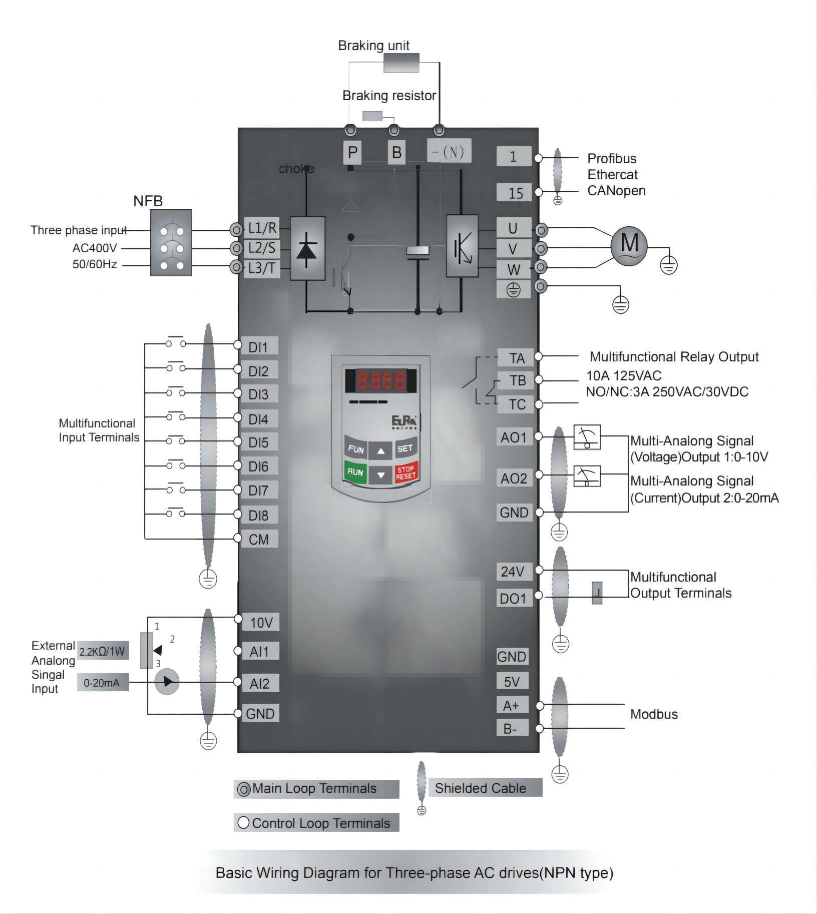
Wiring diagram

Subscribe to our weekly newsletter and receive exclusive offers on products you love!
 X
X


 Gold Supplier


