


♦Extra smooth movement
♦Low drive & motor heating
♦Step & direction or CW/CCW control
♦DSP-based stepper control technology
♦Automatic motor identification and self configuration
♦Semi-closed chassis can adapt to harsher environment.
♦Provides energy-saving semi-automatic current lock function;
♦Built-in temperature protection and overcurrent protection.
Microstep Motor Driver DM542 DM556
DM542/DM556 is a multi-functional fully digital stepper driver based on DSP with advanced control algorithm. It brings unique system smoothness, delivers optimal torque and eliminates mid-range instability. Motor self-test and automatic parameter setting technology provide the best response to different motors and are easy to use. The drive motor runs quieter, generates less heat and provides smoother movement than most drives on the market.
Technical Specification
| Input voltage: | DC 24~50V input |
| Output current: | less than 4 amperes |
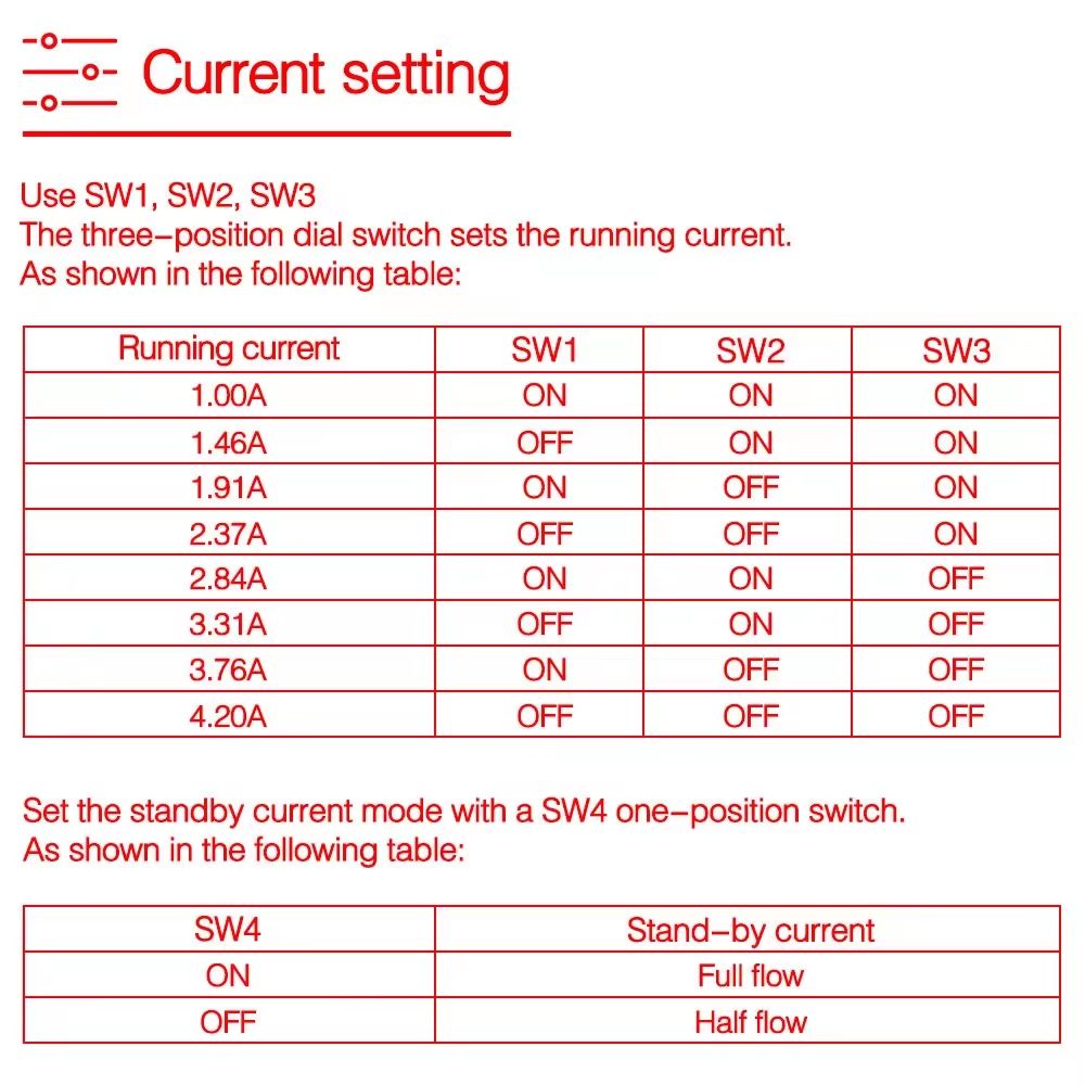
| Output current: | 1.0A~4.2A |
| Power consumption: | power consumption: 80W |
| internal insurance: 6A | |
| Temperature: | working temperature -10~45℃; |
| storage temperature -40℃~70℃ | |
| Humidity: | no condensation, no water droplets |
| Gas: | non-flammable gas and conductive dust |
| Weight: | 200 grams |
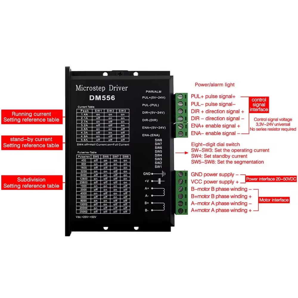
Control signal interface:
1. Definition of control signal
PLS+: Step pulse signal input positive terminal or positive step pulse signal input positive terminal
PLS-: Step pulse signal input negative terminal or positive step pulse signal input negative terminal
DIR+: Step direction signal input positive terminal or reverse step pulse signal input positive terminal
DIR-: Step direction signal input negative terminal or reverse step pulse signal input negative terminal
ENA+: Offline enable reset signal input positive terminal
ENA-: Offline enable reset signal input negative terminal
When the offline enable signal is valid, the drive fault is reset, any valid pulse is prohibited, the output power element of the drive is turned off, and the motor has no holding torque
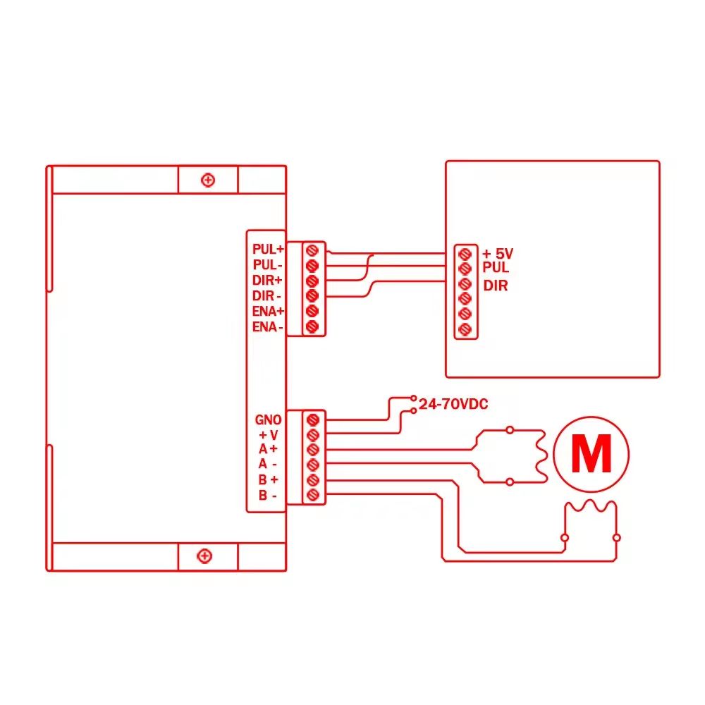
2. Control signal connection
The control signal of the host computer can be effective at high level or at low level. When high is effective, connect the negative ends of all control signals together as the signal ground, when low, connect the positive ends of all control signals together as the signal common end. Now take the open collector and PNP output as an example, the interface circuit diagram is as follows:
FAQ
Can you produce according to the samples or drawings?
Yes, we can produce by your samples or technical drawings. We can build the molds and fixtures.
What is the lead time?
For standard models, lead time is about 3~5 days after order confirmed and payment received.
For OEM orders, the delivery is about 2~3 weeks after data confirmed and payment received.
How to solve the quality problems after sales?
Take photos or videos of the problems and send to us.
We will make a satisfied solution for you within 24 hours after we confirm the problems.

Subscribe to our weekly newsletter and receive exclusive offers on products you love!
 X
X


 Gold Supplier


