|
14-bit and 16-bit resolution |
 |
|
4′ and 2′ accuracy |
|
|
2VA output drive capacity |
|
|
Low radius vector error (0.03%) |
|
|
Equipped with overvoltage protection and short-circuit protection |
|
|
Provided with telemetric output pin |
|
|
Without the need of external adjustment |
|
|
Pin-to-pin compatibility with DRC1745/1746 product of AD company |
Drive synchro/resolver; antenna system; servo system; integrated navigation system; cannon control system; aircraft and warship simulator.
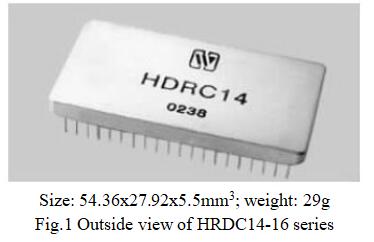
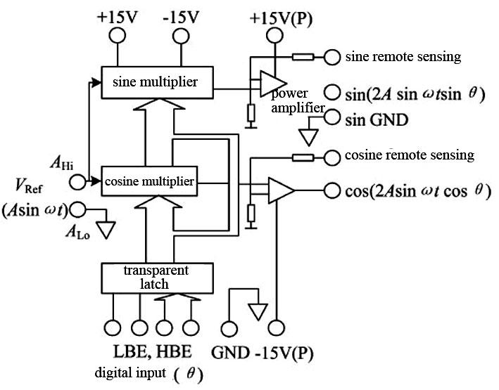
HDRC14/HDRC16 series product is digital to resolver converters or digital to synchro converters of hybrid integrated circuit structure equipped with built-in power amplifier which can drive 2VA load. The load can be inductive load, capacitive load or resistive load, and it is provided with overcurrent and overvoltage protection. The output of converter can directly drive the resolver, and can also drive the control transformer of synchro by connecting a, external transformer.
The unique performance of HDRC14/HDRC16 series product is sine and cosine telemetric output. Thus, when performing long-line drive, it can ensure the precision of converted output signal.
HDRC14/HDRC16 series products are equipped with internal latch, which is controlled through high bit enable end HBE and low bit enable end LBE, and can be connected with data bus conveniently.
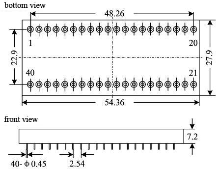
HDRC14/HDRC16 series products are dual in-line 40-pin metal package.
|
Table 1 Rated conditions and recommended operating conditions |
|
|
Absolute max. rated value |
Supply voltage Vs: ± 7.25V Logic voltage VL: +5.5V Storage temperature range: -65℃~+150℃ |
|
Recommended operating conditions |
Supply voltage Vs: ± 5V Logic voltage VL: +5V Reference frequency f: 400Hz~2000Hz Range of operating temperature TA: -55℃~125℃ |
|
Table 2 Electric characteristics |
||||||
|
Characteristic |
HDRC14 |
HDRC16 |
Unit |
Remarks |
||
|
Min. |
Max. |
Min. |
Max. |
|||
|
Resolution |
- |
14 |
- |
16 |
bit |
|
|
Angle error |
- |
±5.3 |
- |
±2 |
Angular minute |
|
|
Analogue reference input |
3.23 |
3.57 |
3.23 |
3.57 |
V |
|
|
Signal output of resolver |
6.46 |
7.14 |
6.46 |
7.14 |
V |
|
|
Gain (VRef-Vo) |
1.999 |
2.001 |
1.999 |
2.001 |
V |
|
|
Temperature coefficient of output gain |
- |
25 |
- |
25 |
PPM/℃ |
|
|
Analogue input frequency range |
0 |
2.6 |
0 |
2.6 |
kHz |
|
|
Analogue input impedance |
10.2 |
- |
15.9 |
- |
kΩ |
|
|
Analogue output impedance |
- |
0.2 |
- |
0.2 |
Ω |
|
|
Output power |
- |
2 |
- |
2 |
VA |
|
|
Radius vector error |
- |
±0.03% |
- |
±0.03% |
- |
|
|
Type of digital input |
Parallel binary code (TTL level) |
Parallel binary code (TTL level) |
- |
|
||


 ; then plus the additional power consumption of the transformer, the total power consumption is 1.48VA.

|
Pin |
Symbol |
Function |
Pin |
Symbol |
Function |
Pin |
Symbol |
Function |
|
1 |
D1(MSB) |
1st bit digital input |
13 |
D13 |
13th bit digital input |
28 |
GNDA |
Analog ground |
|
2 |
D2 |
2nd bit digital input |
14 |
D14(LSB) |
14th bit digital input |
29 |
V- |
-15V Power supply |
|
3 |
D3 |
3rd bit digital input |
15 |
D15 |
15th bit digital input |
30 |
V+ |
+15V Power supply |
|
4 |
D4 |
4th bit digital input |
16 |
D16(LSB) |
16th bit digital input |
31 |
V1+ |
+5V Power supply |
|
5 |
D5 |
5th bit digital input |
17-20 |
NC |
No connection |
32 |
LE |
Low 8-bit select enabled |
|
6 |
D6 |
6th bit digital input |
21 |
Vcos |
Cosine output end |
33 |
HE |
High 8-bit select enabled |
|
7 |
D7 |
7th bit digital input |
22 |
Vsin |
Sine output end |
34 |
RLo |
Low end of reference input |
|
8 |
D8 |
8th bit digital input |
23 |
V+P |
+15V pulsating power |
35 |
RHi |
High end of reference input |
|
9 |
D9 |
9th bit digital input |
24 |
V-P |
-15V pulsating power |
36 |
Case |
Case ground |
|
10 |
D10 |
10th bit digital input |
25 |
cos telemetry |
Cosine telemetric end |
37-40 |
NC |
No connection |
|
11 |
D11 |
11th bit digital input |
26 |
sin telemetry |
Sine telemetric end |
|
|
|
|
12 |
D12 |
12th bit digital input |
27 |
GNDS |
Signal ground |
|
|
|
|
Bit/(MSB) |
Angle |
Bit/(MSB) |
|
Angle |
Bit/(MSB) |
Angle |
|
1 |
180.000 0 |
7 |
|
2.812 5 |
13 |
0.043 9 |
|
2 |
90.000 0 |
8 |
|
1.406 3 |
14 (for 14-bit LSB) |
0.022 0 |
|
3 |
45.000 0 |
9 |
|
0.703 1 |
15 |
0.011 0 |
|
4 |
22.500 0 |
10 |
|
0.351 6 |
16 (for 16-bit LSB) |
0.005 5 |
|
5 |
11.250 0 |
11 |
|
0.175 8 |
|
|
|
6 |
5.625 0 |
12 |
|
0.087 9 |
|
|
|
(1) Signal output type of resolver |
(2) Signal output type of synchro (fig.5) |
 |
|

|
Case model |
Header |
Header plating |
Cover |
Covering plating |
Pinmaterial |
Pin plating |
Sealing style |
Notes |
|
UP5428-40 |
Kovar (4J29) |
Ni/Au |
Iron/ nickelalloy (4J42) |
Ni/Au |
Kovar (4J29) |
Ni/Au |
Matchedseal |
|

 X
X