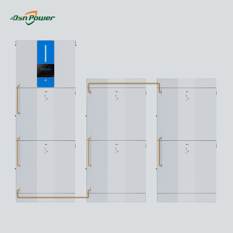
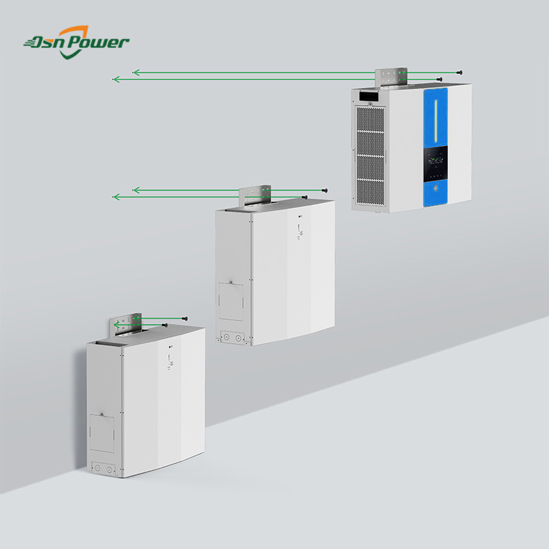
1.Easy Install
OSN All-In-One design install battery module and inverter into.
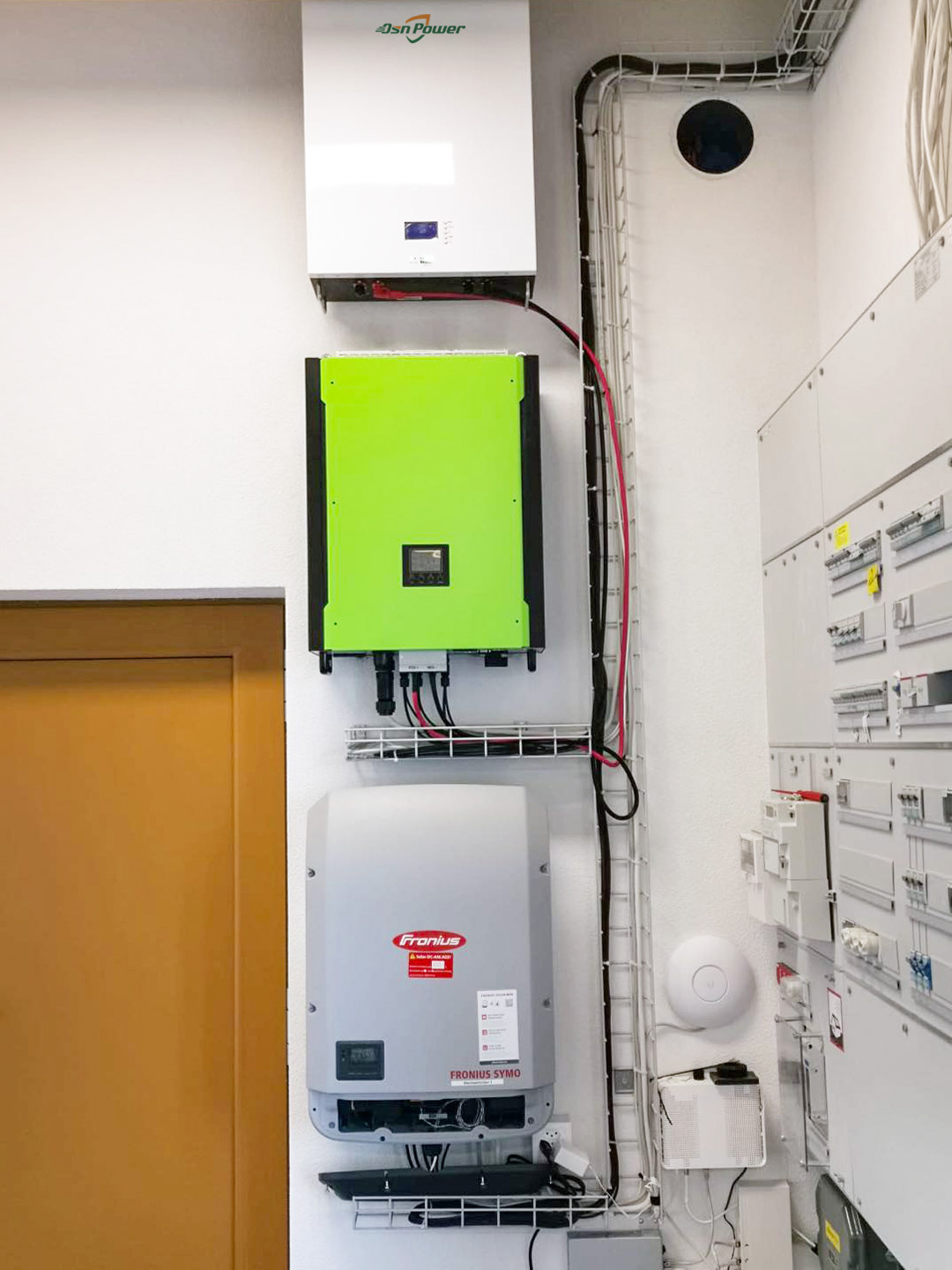
2.DC & AC CouplingProduct Name
New Design Powerwall Battery LiFePO4 48V 50KWH Energy Storage integrated battery inverter 5.5kw
Product introduction
|
•Pure sine wave output |
|||
|
•Self-consumption and Feed-back to the Grid |
|||
|
•Programmable supply priority for PV, battery or Grid |
|||
|
•User-adjustable battery charging current |
|||
|
•Programmable multiple operation modes: Grid-tie, off-grid and grid-tie with backup |
|||
|
•Built-in timer for various mode of on/off operation |
|
||
|
•Multiple communication for USB, RS232, Modbus, SNMP, GPRS and Wi-Fi |
|||
|
•Monitoring software for real-time status display and control |
|||
|
•Enhance AC/Solar charger to 100A |
|
||
|
•Scalable Li-Ion battery expansion |
|
||
Photo of Powerwall Battery LiFePO4 48V 50KWH Energy Storage integrated battery inverter 5.5kw


Datasheet of 50kwh Lithium 48V 100AH LiFePO4 Solar Energy Storage Battery Bank
(Pls note Each 5.5KW inverter can stack 13 max. battery modules( 48V 8KWH),
and max. 6 inverters can be paralleled. It shows: 13*6=78 modules max.)
Below spec for 1pc 5.5KW inverter integrated 6 battery modules total 50KWH energy storage.
|
It’s applicable to Grid-tie & Hybrid & Off-Grid |
||
|
Item |
Specification |
Comments |
|
Model |
OSN-5.5KW |
|
|
Max. DC Power |
6500W |
|
|
Nominal DC voltage |
360Vdc |
|
|
Max. Input voltage (Maximum PV open voltage) |
500Vdc |
|
|
System start-up voltage |
116Vdc ± 10Vdc |
PV establish control power |
|
Initial feeding voltage |
150V ±10Vdc |
|
|
Working voltage range |
100Vdc (±10Vdc) ~ 500Vdc (-10Vdc+0Vdc) |
DC voltage range that inverter can feed power to grid |
|
MPPT voltage range |
120 ~ 450Vdc(±10Vdc) |
|
|
Max. of Pi/p |
Rated load |
250Vdc~450Vdc |
|
P = 13*Vi/p |
<250Vdc |
|
|
P = 28000-55*Vi/p |
>450Vdc |
|
|
Shutdown voltage |
<70V typical |
|
|
Number of MPP Trackers |
2 |
|
|
Max. DC Input current / per string |
13A |
|
|
Max. PV Charging current |
100Amp |
|
|
Strings per MPP Tracker |
A:1 |
|
|
Item |
Specification |
Comments |
|
Model |
OSN48-50KWH |
|
|
|
||
|
Nominal Voltage(V) |
48V |
|
|
Fully Charge Voltage(FC) |
52.5V Defined in this DOC :FC=52.5V |
For battery pack |
|
Fully Discharge Voltage(FD) |
34.5V Defined in this DOC FD=34.5V |
For battery pack |
|
Typical Capacity(Ah) |
1000Ah |
At 0.2C discharge rate |
|
Discharge Current
|
120A |
700A Peak 5ms 150%*120=180A 4mins 160%*120=192A 1min |
|
Recommend UPS Discharge Terminated Voltage |
37.5V |
Adjust to UPS |
|
Recommend Charge Voltage |
52.5V |
When max cell voltage reaches to 3.55V, battery pack will inform charger to stop charging or the battery pack will turn off CHG after the max cell voltage over 3.55V for 20mintues |
|
Maximum Charge Current |
50A |
|
|
Recommend Charge Current (Battery Pack could also send commend to charger to adjust the charge current according to existing battery pack temperature) |
20A |
Battery pack at 0℃~5℃ |
|
30A |
Battery pack at 5℃~45℃ |
|
|
20A |
Battery pack below 45℃ |
|
|
Standard Charge Method |
0.2C CC(constant current)charge to FC, then CV(constant voltage FC)charge till charge current decline to ≤0.05C. |
|
|
Inner Resistance |
≤20mΩ |
Between positive and negative polar of discharge port |
|
Operation Environment Temperature range ℃ |
Charge: 0℃~50℃ |
Temperature Protection value is 0℃ & 60℃ on cell surface |
|
Discharge: 0℃~+50℃ |
Temperature Protection value is -20℃ & 80℃ on cell surface |
|
|
-20℃~25℃ <18 months |
Max. 80%RH |
|
|
25℃~45℃ <3 months |
Max. 80%RH |
|
|
45℃~60℃ <1 month |
Max. 80%RH |
|
|
20±5℃ is the recommended storage temperature |
||
|
Shelf Life |
18 months in ship mode |
-20℃~25℃,Max. 80%RH |
|
Environment humidity Range |
20%RH-80%RH |
|
|
IP requirement |
IP20 |
|
Related products


 X
X