|
Modules includes two DC/DC converters and two Triple-phase brushless motor drive circuits |
 |
|
Built-in three-phase six-leg drive circuit and power amplifier circuit |
|
|
Built-in leak-loope circuit ( leak resistors are not included) |
|
|
The PWM signal, enable control signal and discharge control signal are electrically isolated from the drive circuit |
|
|
To achieve A、C two-phase current signal isolation detection |
|
|
To achieve the power supply voltage detection |
|
|
Realization of shell temperature isolation detection of intelligent power module |
|
No |
Character |
Test Condition VI1=28V±1V VI2 50%TTL square wave -40℃≤Tc≤85℃ |
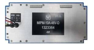
MIPM-10A-48V-D |
Unit |
|||
|
Min |
|
Max |
|||||
|
1 |
Azimuth current detection signal 1VAZ1 |
Output currentI0=(2.5±0.5)A,Triangular hair access |
|
|
|
V |
|
|
Azimuth current detection signal 2VAZ2 |
1.4 |
|
1.6 |
V |
|||
|
Pitch current detection signal 1VEL1 |
1.4 |
|
1.6 |
V |
|||
|
Pitch current detection signal 2VEL2 |
- |
|
- |
V |
|||
|
2 |
Bus voltage detection signal VM |
TA=25℃, Io=(2.5±0.5)Ω |
2.0 |
|
2.4 |
V |
|
|
3 |
+5V |
OutputvoltageV+5V |
RL1=(2.5±0.5)Ω TA=25℃,RL1=(2.5±0.5)Ω BW≤20MHZ |
4.80 |
|
5.20 |
V |
|
Output currentI+5V |
- |
|
2.0 |
A |
|||
|
Ripple voltage VRI |
- |
|
100 |
mV |
|||
|
No |
Character |
Test Condition VI1=28V±1V VI2 50%TTL square wave -40℃≤Tc≤85℃ |
MIPM-10A-48V-D |
Unit |
|||
|
Min |
|
Max |
|||||
|
4 |
-15Vsupply |
V-15V |
RL2=(45+1)Ω TA=25℃,RL2=(45±1)Ω BW≤20MHZ |
-15.20 |
|
-14.80 |
V |
|
I-15V |
- |
0.33 |
A |
||||
|
Ripple VR2 |
- |
100 |
mV |
||||
|
5 |
+15V supply |
V+15V |
RL2=(45+1)Ω TA=25℃,RL2=(45±1)Ω BW≤20MHZ |
14.80 |
|
15.20 |
V |
|
I+15V |
- |
|
0.33 |
A |
|||
|
RippleVR3 |
- |
|
100 |
mV |
|||
|
6 |
A continuous working current IOA |
|
2.5 |
|
- |
A |
|
|
7 |
B continuous working current IOB |
|
2.5 |
|
- |
A |
|
|
8 |
A continuous working current I0A |
TA=25℃ |
4.0 |
|
- |
A |
|
|
9 |
B continuous working current I0B |
TA=25℃ |
4.0 |
|
- |
A |
|
|
No |
symbol |
Designation |
No |
symbol |
Designation |
|
1 |
AZITEST1 |
Azimuth current detection signal 1 |
11 |
AZITEST2 |
Pitch current detection signal 1 |
|
2 |
GND |
Detection signalGround |
12 |
GND |
Detection signal Ground |
|
3 |
ELITEST1 |
Azimuth current detection signal 2 |
13 |
ELITEST2 |
Pitch current detection signal 2 |
|
4 |
GND |
Detection signal Ground |
14 |
GND |
Detection signal Ground |
|
5 |
VOLTEST |
Voltage detection Signal |
15 |
TEMPTEST |
Internal temperature detection signal |
|
6 |
GND |
±15VPower ground |
16 |
GND |
Detection signal Ground |
|
7 |
V-15V |
-15V Voltage |
17 |
AAP+ |
28V Power control signal |
|
8 |
+V15V |
+15V Voltage |
18 |
AAP |
28V Power control signal |
|
9 |
GND |
+5VPower ground |
19 |
GND |
+5V Power ground G |
|
10 |
+V5V |
+5VPowerVoltage |
20 |
+V5V |
+5VPower voltage |


|
Lead |
Symbol |
Function |
Output line |
|
11 |
BH3 |
B road C |
CC(2) |
|
12 |
BH2 |
B road B |
BB(2) |
|
13 |
BH1 |
B road A |
AA(2) |
|
14 |
AH3 |
A road C |
CC1 |
|
15 |
AH2 |
A road B |
BB1 |
|
16 |
AH1 |
A road A |
AA1 |
")

Subscribe to our weekly newsletter and receive exclusive offers on products you love!
 X
X


 Gold Supplier