♦Dual-core processing efficiency is higher, the high motor runs smoothly, the vibration when stopping is lower, and the response is faster
♦ Simple and easy-to-understand menu display
♦ The DB series plug for convenient wiring, simple operation and easy welding
♦Supports CANopen/EtherCAT bus control, Meet the needs of high-end equipment.
♦SD20 supports fully closed-loop control and gantry synchronization, and the driver can adapt to a wider range of places.
SCH-SD20-G Universal servo
SD20-G Series Servo Drives is a high performance drive particularly suitable for general use. It has a 3.0kHz frequency response, which could meet the wide range of customer's requirement. The feedback options are incremental encoder, absolute encoder and resolver.
The rich functionality includes full close loop, multi-position control, gain switchover, moving fixed-length cutting, etc.
Built-in PLC is open for customer to make simple programming.
Widely used in robots, CNC machine tools, textiles, packaging and other industries.
Technical Specification
| Item | Content | |
| Input power | S2/T2 series | 220VAC-15~+10%50/60Hz |
| T3 Series | 380~440VAC-15~+10%50/60Hz | |
| Control mode | Pt:Position pulse mode Pr:internal register position mode | |
| Sz:analog speed mode Sr:internal register speed mode | ||
| Tz:analog torque mode Tr:internal register torque mode | ||
| Energy consumption braking | Built-in or external brake resistance (external is optional) | |
| M1 model does not have built-in brake resistance; | ||
| 7.5KW and above drivers do not have built-in brake resistance | ||
| The rest have built-in brake resistors | ||
| Control characteristics |
control method | Permanent magnet synchronous motor; |
| speed response frequency | Permanent magnet synchronous servo: 1.2KHz; | |
| velocity volatility | ±0.01% (load 0~100%) | |
| speed fluctuation | Permanent magnet synchronous motor: ±0.01% (VC, load 0~100%): | |
| Speed ratio | 1:10000 | |
| Input pulse frequency | 1、500KHz (differential): 200KHz (open collector): | |
| 2、The acceptable frequency for high-speed pulse circuit is 4Mz (differential type); | ||
| Input signal | Control input | Servo enable,alarm reset,command pulse Clear,command pulse Disable forward turn disable,Reverse disable,positive torque limit,reverse torque limit,internal speed selection,internal position trigger,origin/mechanical origin search trigger,zero speed clamp,etc |
| Encoder | 1.Absolute value encoder; | |
| 2.Incremental encoder; | ||
| 3 Rotary transformer; | ||
| 4.BiSS-C; | ||
| 5.Magnetic knitting | ||
| 6.Hiperface; | ||
| Output Signal | Control output | Servo ready,servo alarm,position arrived,speed arrived,electromagnetic lock output rotation check out,speed limit medium,origin found,torque limit medium |
| Encoder signal frequency division output |
Three output methods: 1,encoder Z phase collector open circuit output; 2,encoder A,B phase frequency division signal differential output (not solated)arbitrary frequency division;Z phase no frequency output; 3,Z pulse time expansion function; | |
| Position control | Input mode | Two-phase orthogonal pulse,forward pulse+reverse pulse,pulse+direction,internal register |
| Electronic gear ratio | 1、0.01<B/A<100 | |
| 2,support two sets of electronic gear,users can choose or switch according to actual needs | ||
| Analog speed contro | -10V~+10V analog speed signal input,can change the setting range;through the function code;Instruction source is optional; | |
| Analog torque control | -10V~+10V analog torque signal input,you can change the setting range;through the function code;Instruction source is optional; |
|
| Add/slow down | Parameter setting acceleration and deceleration time 1~30000ms (from 0 acceleration to rated speed) | |
| Communications | RS485/RS232 interface,through the connection with PC,servo control parameters setting and monitoring | |
| Paramete setting | Keyboard input | Parameter adjustment can be operated with four keys and displayed via a 5-digit nixie tube |
| Upper computer Settings |
The upper computer software running the Ori servo sets the driver parameters through the RS485,RS232 communication interface |
|
| Monitoring function | Output current,bus voltage,motor speed,motor feedback pulse,motor feedback revolution,given pulse,given pulse error,given speed,given torque,analog speed,analog torque,eto | |
| Protection function | Category 1 alarm: main power supply overvoltage, overcurrent, encoder abnormality, emergency stop, torque imbalance, etc. Category II alarm: main power undervoltage, overload, excessive speed error, driver overheating, main circuit power supply phase loss, abnormal pulse control instructions, regenerative braking abnormality, excessive position control error, lithium battery alarm, etc. |
|
| Applicable load inertia | Less than 5 times the inertia of the servo motor | |
Drive component
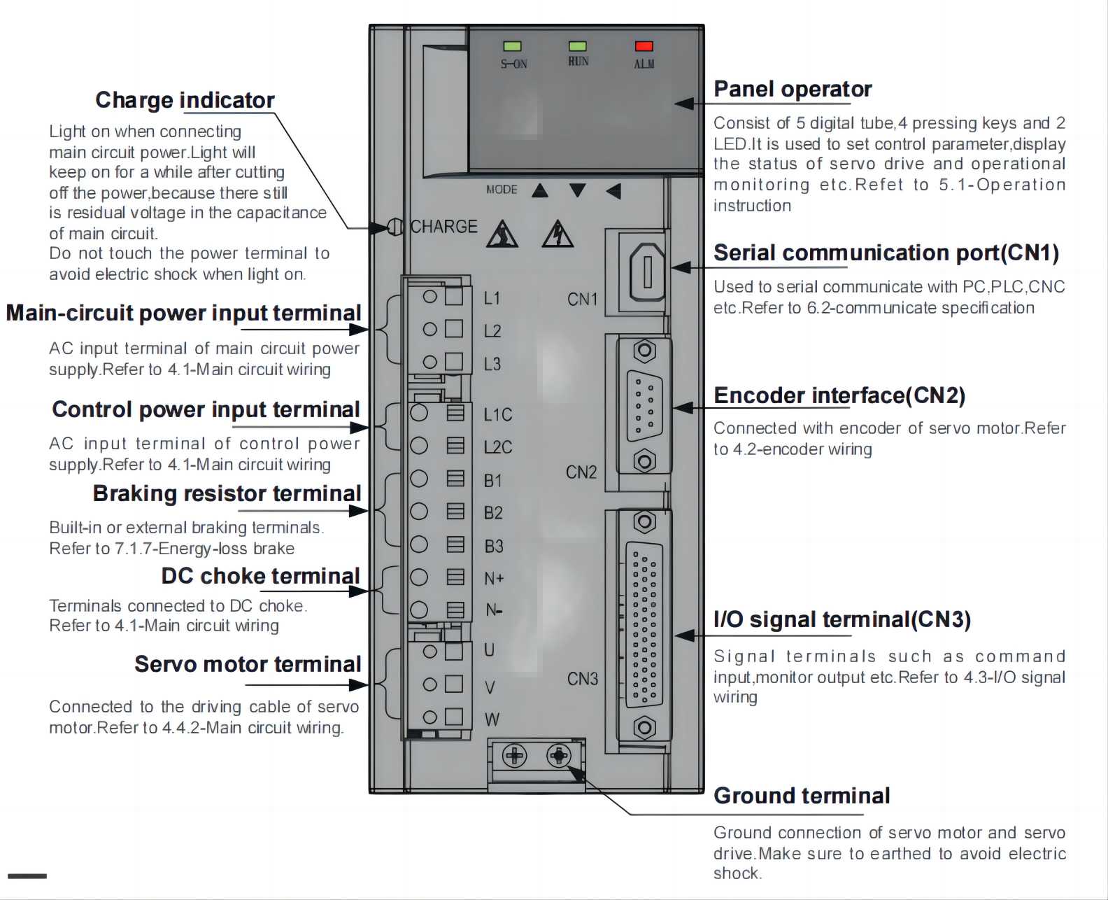
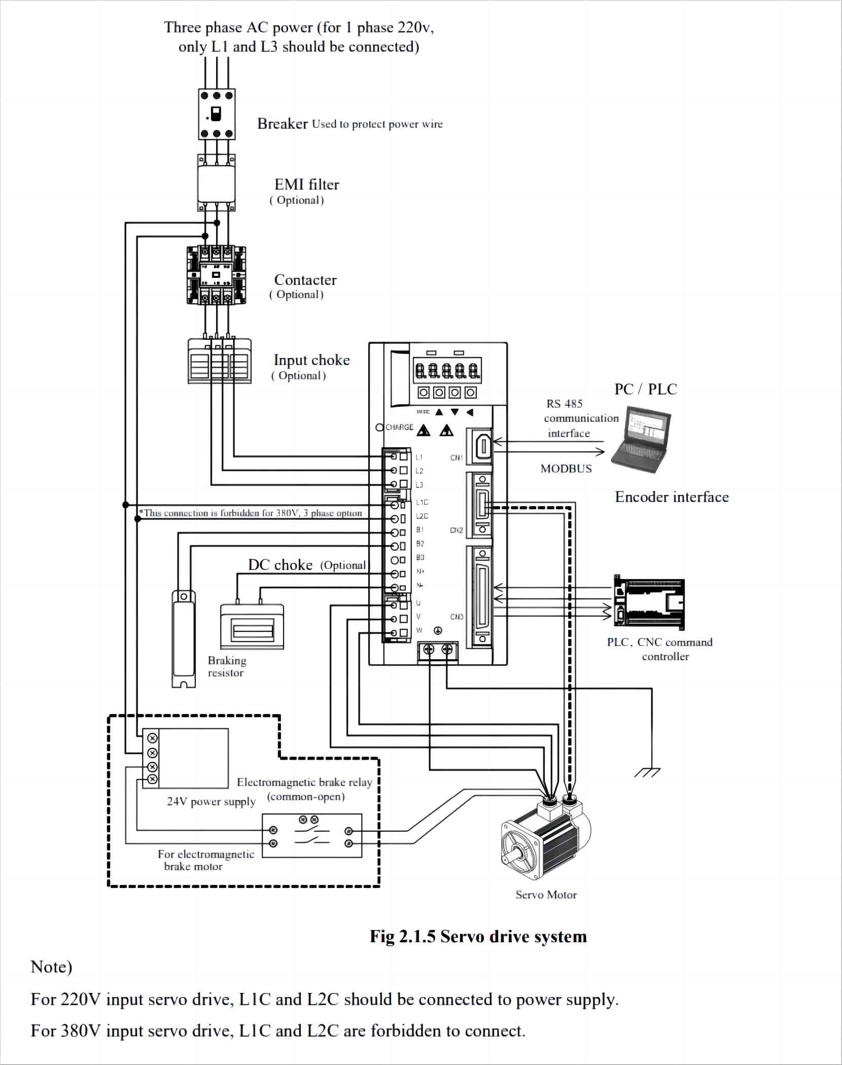
Product wiring diagram
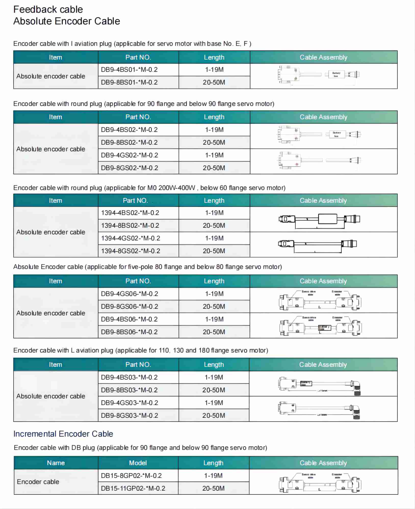
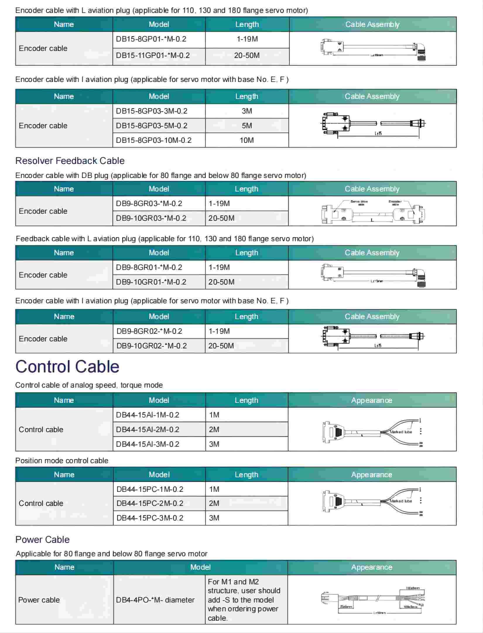
 X
X