Power ratings: 0.2kw-5.5kw
• Best performance/cost ratio, without compromise in reliability and quality
• Compact design, easy to integrate in your environment: DIN rail mounting, contactor-style I/0 Easy to setup: Simple set of optimized parameters for all basic functions and applications
• PID and HVAC functions - safety integrated - MODBUS - open for networking
• Internal EMC filter as standard: Ready for CE market
• Economical mass production on high automated and dedicated SMT lines
• General purpose drive - made for the worldwide market (CE/UL/CCC)
• Approved and certified by European independent bodies
• Built-in STO Function (only available for frame Q2)
SCH-E600 Smart inverter
SCH-E600 is our newest compact inverter. It is designed as easy installation, user-friendly interface, DIN rail mounting, and simple operation.
Technical Specifications
Table2-2Technical Specifications for E600 Series Inverters
| Items | Contents | |
| Input | Rated Voltage Range | 3-phase 380-480V(+10%,-15%)tc l 1-phase 220-240V±15% |
| Rated Frequency | 50/60Hz,Frequency ±5% | |
| Output | Rated Voltage Range | 3-phase 0-INPUT (V) |
| Frequency Range | 0.50~650.0Hz | |
| Control Mode |
Carrier Frequency | 08-6K;Mfr's vale:3K |
| Input Frequency Resolution | Digital setting:0.01Hz,analog setting:max frequency*0.2% | |
| Control Mode | Induction motor:VVVF | |
| Start Torque | 1HZ100% | |
| Overload Capacity | 150%rated current,60 seconds | |
| Torque Elevating | Manual Torque Promotion includes 1-20 curves. | |
| V/F Curve | 3 kinds of modes:beeline type,n-th power type(1.5 th power,1.8 th power,1.9th power,square)and under-defined VVVF curve. |
|
| Startup mode | Start directly | |
| DC Braking | DC braking frequency:0.20-50.00 Hz, braking time:0.00~30.00s |
|
| Jogging Control | Jogging frequency range:min frequency~max frequency jogging acceleration/deceleration time:0.1~3000s |
|
| Auto Circulating Running and multi-stage speed running |
Terminals control can realize 15-stage speed running | |
| Built-in PID adjusting | Easy to realize a system for process closed-loop control | |
| Auto voltage regulation (AVR) | When source voltage changes,the modulation rate can be adjusted automatically,so that the output voltage is unchanged. |
|
| Operation Function |
Frequency Setting | Potentiometer or external analog signal (0~5V,0~10V, 0~20mA,4~20mA);keypad (▲/V keys,terminal external control logic and PC/PLC) |
| Start/Stop Contro | Terminal control,keypad control or communication control | |
| Running Command Channels | 3 kinds of channels from keypad panel,control terminal and MODBUS |
|
| Frequency Source | Frequency sources:given digit,given analog voltage,given analog current and given MODBUS |
|
| Accessorial frequency Source | 0:Memory of digital given 1:External analog All 3:Stage speed adjusting 4:PID adjusting |
|
| Optional | Built-in EMI filter,built-in braking unit | |
| Protection Function |
nput under-voltage,DC over-voltage,over-current,inverter over-load,motor over-load,over heat,analog disconnected protection,etc |
|
| Display | Output frequency,rotate-speed (rpm),output current,output voltage,DC-link voltage,PID feedback,PID setpoint,types of fault,and parameters setting LED indicators showing the working status of inverter |
|
| Fnvironment Conditions |
Equipment Location | In an indoor location,Prevent exposure from direct sunlight,Free from dust,tangy caustic gases,flammable gases,steam or the salt-contented,etc |
| Environment Temperature | -10℃~+40℃ | |
| Environment Humidity | Below 90%(no water-bead coagulation) | |
| Vibration Strength | Below 0.5g(acceleration) | |
| Height above sea level | 1000m or below | |
| Protection level |
IP20 | |
| Applicable Motor |
0.4~22kW | |
Product appearance
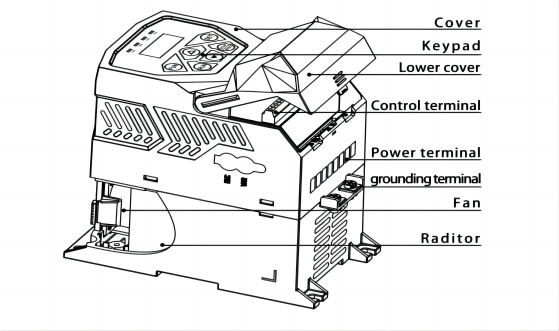
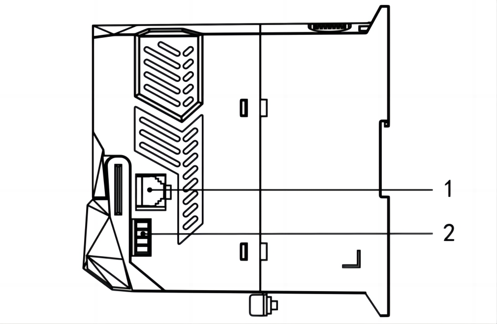
The external structure of E600 series inverter isplastic housings. Wall hanging type isadopted. Good poly-carbon materials are adopted through die-stamping for plastichousing with nice form, good strength and toughness.Taking E600-0030T3for instance, the external appearance and structure are shown as inbelow Fig.
| Structure No. | Content |
| Q1/Q2 structure1 | |
| 1 | 8-core net cable remote keypad interface |
| 2 | RS-485 communication (A+,B-) |
Panel Illustration
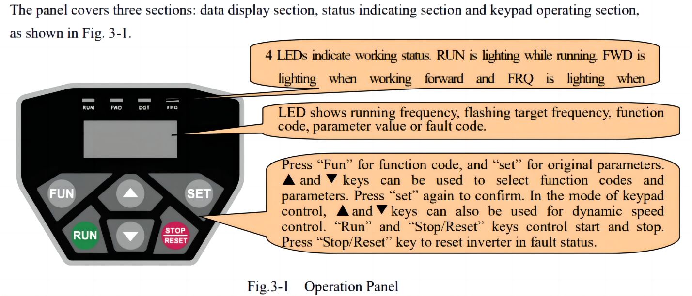
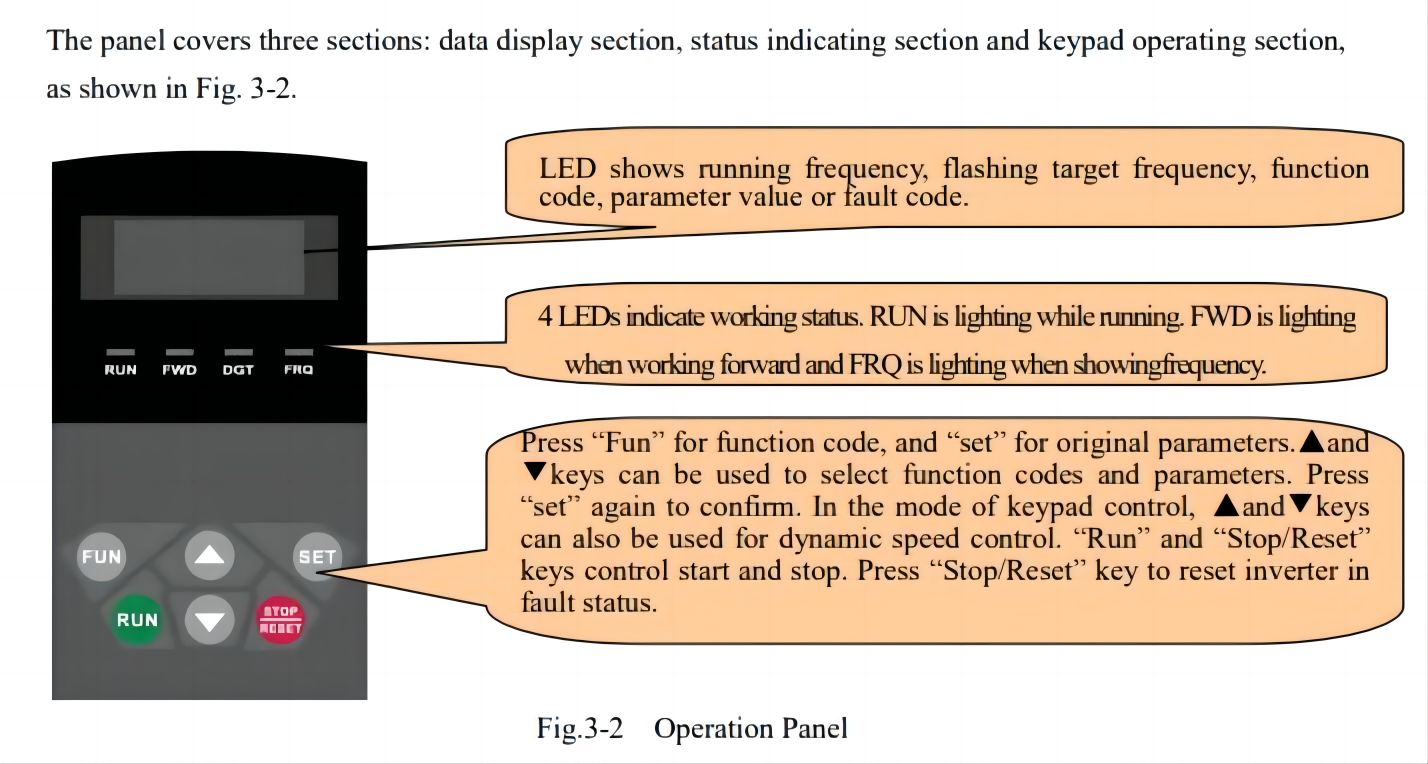
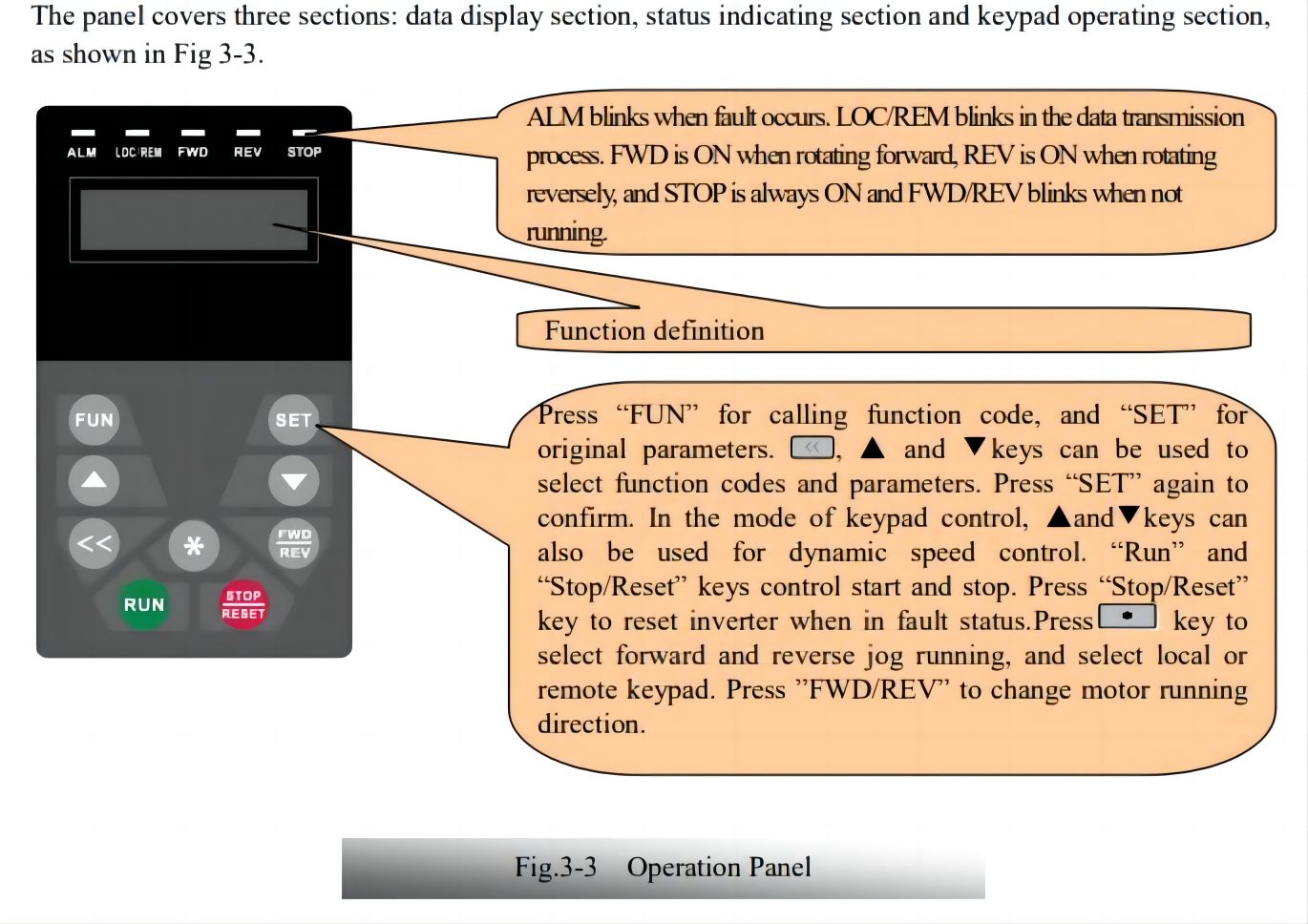
Note:Local panels cannot be pulled out.Please select AAor A6 control panel to realize remote control, which isconnected by 8-core telephone cable.
Table 3-3 Uses of Keys
| Keys | Names | Remarks |
| Fun | Fun | To call function code and switch over display mode |
| Set | Set | To call and save data. |
| ▲ | Up | To increase data(speed control or setting parameters) |
| ▼ | Down | To decrease data (speed control or setting parameters |
| Run | Run | To start inverter |
| Stop/reset | Stop or reset | To stop inverter;to reset in fault status;to change function codes in a code group or between two code groups. |
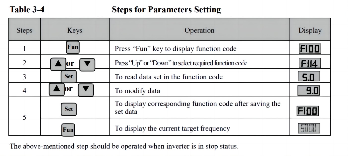
Parameters Setting
This inverter has numerous function parameters, which the user can modify to effect different modes ofoperation control. User needs to realize that if user sets password valid (F107=1), user‘s password must beentered first if parameters are to be set after power off or protection is effected, i.e., to call F100 as per themode in Table 3-4 and enter the correct code. User‘s password is invalid before delivery, and user could setcorresponding parameters without entering password.
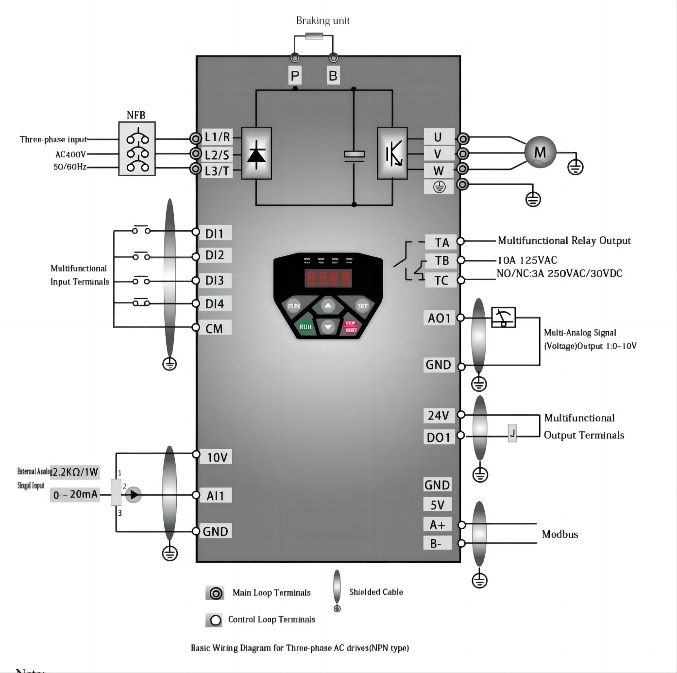
Note:
1. Please only connect power terminals L1/R and L2/S with power grid for single-phase inverters.
2. 485 communication port has built-in standard MODBUS communication protocol. Communication port is on therightside of inverter.
3. The contact capacity is 10A/125VAC. NO/NC: 3A 250VAC/30VDC.
FAQ
Can I get some samples?
Yes, Sample order is available for quality check and market test. But you have to pay the express cost.
What's delivery time?
It usually takes about 3-5 working days for small order and 10-15 days for big order.
How to solve the quality problems after sales?
Take photos or videos of the problems and send to us.
We will make a satisfied solution for you within 24 hours after we confirm the problems.
 X
X