♦Pulse mode: monopulse/double-pulse/orthogonal pulse
♦Signal level: 3.3~24V compatible; series resistance not necessary for the application of PLC
♦Power voltage: 110-230V AC;220V AC recommended
SCH-3R130 three-phase stepper motor driver
The 3R130 digital 3-phase stepper drive is based on TI's 32-bit DSP platform and integrated with the micro-stepping technology and the patented three-phase demodulation algorithm. With the features of low noise, low vibration, low heating and high-speed high torque output, it allows the three-phase stepper motor to deliver full performance benefits.
Typical application: carving machine, labeling machine, cutting machine, plotter, numerical control machine, laser, automatic assembly equipment
Product Specification
| Pulse mode | Single pulse/double pulse/orthogonal pulse | ||
| Signal level | 3.3~24V compatible,no series resistance required for PLC applications | ||
| Power supply voltage | 110-230V AC | ||
| Typical Application | Engraving machines, cutting machines, silk screen equipment, CNC machine tools, automatic assembly equipment, etc | ||
| Operating voltage range | 110VAC-230VAC | ||
| Operating current range | 2.4~7.0A | ||
| Matching motor | 110 three-phase series motor, 130 three-phase series motor | ||
| Rich control signal interface | PUL&DIR,CW+CCW | ||
| Control signal interface level | 3.3V-24VDC | ||
| The entire series provides 8 levels of current and 16 levels of subdivision settings. | |||
| Adaptive parameter identification enables the motor to have high-quality noise and performance under various voltage conditions | |||
| High reliability, providing overvoltage, overcurrent and other protection functions. | |||
Driver function
| Driver function | Operating instructions |
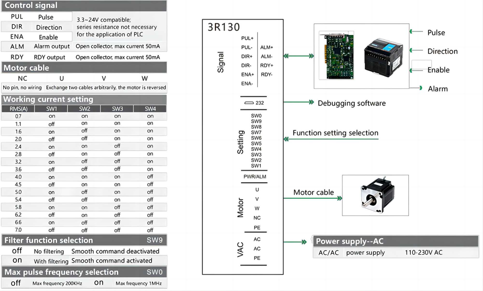
| Microstep fine score setting | SW5-SW8 Four dip switches are used to select a total of 16 micro step subdivisions. Please select the correspondingsubdivision by referring to the driver panel, and ensure that the drive is not active when setting. |
| Output current setting | SW1-SW4 Three dip switches are used to select a total of 16 output currents. Please select the corresponding subdivision against the driver panel, and ensure that the driver is not active when setting. |
| Automatic half-current function | SW9 Dip switches are used to ssmoothing function of the drive. off means to turn this feature offand on means to turn it on. SWO is used to select the bandwidth of the drive, the maximum pass pulse frequenc!is 200KHZ when off, and the maximum pass pulse frequency is lMHZ when on. |
| Signal interface | PUL+ and PUL- for the positive and negative ends of the control pulse signal, DlR+ and DlR- for thepositive and negative end of the direction signal; ENA+ and ENA - for the positive and negative ends ofthe enable signal., AlM+ and ALM- for the positive and negative ends of the alarm signal and RDy+ andRDY- for the positive and negative ends of the place signal. |
| Motor interface | U, V, and W correspond to the motor winding wires U, V, and W. By arbitrarily swapping two of the three winding wires, the direction of the motor can be changed, and the PE grounding wire can be changed. |
| Power interface | The recommended operating voltage range of 3R130 is AC 110-230V. It is recommended to add a filter (EMIFILTER) before the power supply circuit. |
| ndicators | The drive has red and green indicator lights. The green light is the power indicator light, which flashes when the driver is powered on; the red light is the fault indicator light, which flashes when an overvoltage or overcurrent fault occurs. After the fault is cleared, the red light goes out. When the drive fails, the fault can only be cleared by powering on and re-enabling it. |
SCH-3R130 Connections

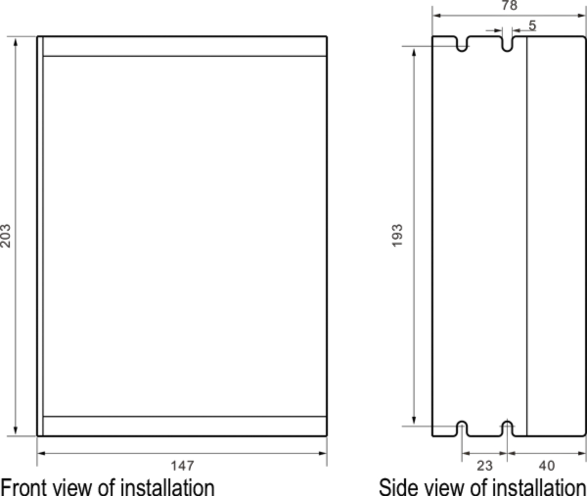
Product Dimensions

FAQ
Can we accept samples customized?
No problem for samples order, and welcome your testing before your big order.
OEM and ODM are available?
Yes, we accept customized products
Can I get a lower price if I order large quantities?
Yes, Cheaper prices with bigger size orders, please contact us and we will give you a quatation.
 X
X