MPWM600-1 PWMA

Sales MPWM600-1 PWMA

  • Max.Input Vol : 60V
  • Max Current : 20A
  • Function : BRUSHED DC MOTOR CONTROLLER

Product Detail  

1. Features

Wide input voltage:20V~60V

TTL Square wave input
Max continuous input current 30A

2. Scope of application of MPWM600-1 PWMA

DC motor drive control
Drive the reactive load

3. Descriptions of MPWM600-1 PWMA

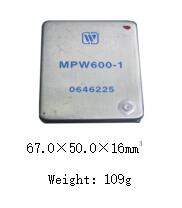
MPW600-1 PWMA is a PCB circuit board assembly of finished components with metal shell package module circuit. The amplifier accepts tow TTL signals, mainly for PWM signal power amplification, the output of the amplified signal can be used as the motor drive signal. The module has the characteristics of simple structure, convenient debugging, in-proved reliability and relative low cost. With the development of modern electronic technology, the module is widely used in the applications such as servo structure, the motor control, drives the reactive load, drives the low frequency sonar, drives the piezoelectric transformation Equipment, off-line drive, CD welding control .

4. Technical Specifications of MPWM600-1 PWMA

Absolute Maximum Ratings

Recommended working conditions

Supply voltage +Vcc:15V

Supply voltage +Vs:80V

Working frequency fo:1KHZ~20KHZ

Storage temperature Tstg:-55℃~100℃

Junction Temperature(Tj):<150℃

Supply voltage +Vcc:12V±1.2V

Supply voltage +Vs:20V~60V

Working frequency fo:10KHZ

Operating temperature(Tc):-55℃~85℃


Form 2 Electrical characteristics

No.

Parameter

-55℃≤Tc≤85℃

MPW600-1

Unit

Min

Typical

Max

1

Working Frequency

-

9.5

10

10.5

KHZ

2

Continuous working current

85℃or less(case temperature)

-

3

-

A

3

Vcc

-

10.8

-

13.2

V

4

Vs

-

20

-

60

V

5

Static current Icc

Io=0

-

-

50

mA

6

Operating temperature (Case temperature TC)

-

-55

-

+85


5. Lead function description of MPWM600-1 PWMA

Lead function description
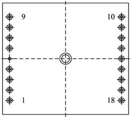
Fig 2 Bottom view

Form 3 Lead description

No.

Symbol

Function

No.

Symbol

Function

1

V in1+

Square waveinput1+

10

VCC

+12V

2

V in1-

Square waveinput1-

11

DIS

Protection

3

V in2-

Square waveinput2-

12

OUT1

Output 1

4

V in2+

Square wave  input2+

13

OUT1

Output 1

5

NC

NC

14

OUT2

Output 2

6

NC

NC

15

OUT2

Output 2

7

GNDC

Case ground

16

VSS

VMOS source

8

NC

NC

17

GND

60V、12V ground

9

NC

NC

18

VS

Mptor power supply


6. Circuit block diagram of MPWM600-1 PWMA

Circuit block diagram
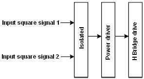
Fig 3  Circuit block diagram

7. Typical Connection Diagram of MPWM600-1 PWMA


Typical Connection Diagram
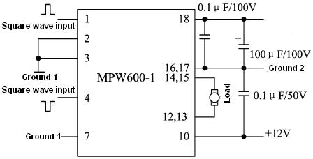
Fig 4 typical connection diagram

Power supply VS should have sufficient bypass capacitors to ensure proper operation, otherwise it may be unstable and reduce efficiency, and the output may be oscillated. Vcc power supply should be connected  a 0.1μF/50V ceramic capacitor with GND, Vs power supply should be connected a 0.1μF/100V ceramic capacitor and 100μf/100V Tantalum capacitor with GND, All bypass capacitors should be connected as close as possible to the corresponding power supply root.
Pin 11 is protection terminal ,users can connect with external protection circuit according to the control requirements. When the pin connect with high voltage(>2.7V),No output for protection When the pin is suspended, it works properly.

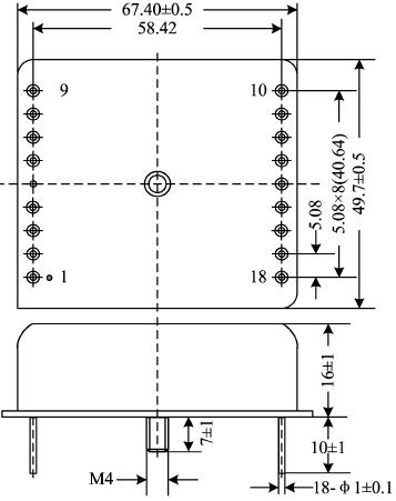
8. Package Specifications(Fig 5,Unit mm) of MPWM600-1 PWMA


Package Specifications(Fig 5,Unit mm)
Application notes please refer to the appendix, must read it carefully.
Leave A Message
If you are interested in our products and want to know more details,please leave a message here,we will reply you as soon as we can.
X

Home

Supplier

Leave a message

Leave a message

If you are interested in our products and want to know more details,please leave a message here,we will reply you as soon as we can.