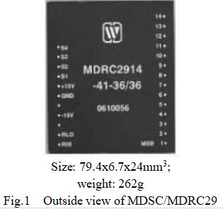
1.Features (see Fig. 1 for outside view, and Table 1 formodels)
|
Compatible with DTL/TTL/CMOS level |
 |
|
12-bit, 14-bit and 16-bit resolution |
|
|
Short-circuit and overload protection |
|
|
Metal case, with good heat rejection |
|
|
Output power: 5W |
Table1 Product models
|
12-bit |
14-bit |
16-bit |
|||
|
Synchro |
Resolver |
Synchro |
Resolver |
Synchro |
Resolver |
|
MDSC2912-411 |
MDRC2912-418 |
MDSC2914-411 |
MDRC2914-418 |
MDSC2916-411 |
MDRC2916-418 |
|
MDSC2912-412 |
MDRC2912-438 |
MDSC2914-412 |
MDRC2914-438 |
MDSC2916-412 |
MDRC2916-438 |
|
MDSC2912-421 |
MDRC2912-414 |
MDSC2914-421 |
MDRC2914-414 |
|
MDRC2916-414 |
|
MDSC2912-422 |
MDRC2912-415 |
MDSC2914-422 |
MDRC2914-415 |
|
MDRC2916-41-36/11.8 |
|
|
|
|
|
|
MDRC2916-415 |
|
Max. absolute rating value |
Supply voltage +VS: +13.5~+17.5V Supply voltage -VS: -17.5~-13.5V Storage temperature range: -40~100℃ |
|
Recommended operating conditions |
Supply voltage +VS: +14.5~+16.5V Supply voltage -VS: -16.5~-14.25V Reference voltage (effective value) VRef*: 115V±5% Signal voltage (effective value) V1*: 90V±5% Reference frequency f*: 400Hz±10% Range of operating temperature TA: -40℃~85℃ |
|
Parameter |
MDRC/DSC2912 |
MDRC/DSC2914 |
MDRC/DSC2916 |
Unit |
|||
|
Enterprise military standard (Q/HW30857-2006) |
|||||||
|
Resolution |
12-bit |
14-bit |
16-bit |
Bit |
|||
|
Accuracy |
±8 |
±4 |
±4 |
Minute |
|||
|
Digital input |
5 |
0 |
5 |
0 |
5 |
0 |
V |
|
Reference voltage (effective value) |
26, 36, 115V±10%﹡ |
V |
|||||
|
Reference frequency |
50, 400, 1.2K, 2K﹡ |
Hz |
|||||
|
Output signal voltage (Effective value) |
11.8, 26, 36, 90 (line-line, resolver or synchro)﹡ |
V |
|||||
|
Output power |
5 |
W |
|||||
 |
 |
|
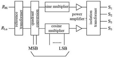
Fig.2 Schematic diagram for DSC converter |
Fig.2 Schematic diagram for DRC converter |


7. MTBF curve (Fig. 5) of MDSC/MDRC29 Series Digital to Synchro Converters or Digital to Resolver Converters |
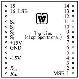
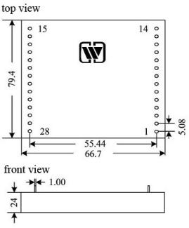
8. Pin designation (Fig. 6, Table 4) of MDSC/MDRC29 Series Digital to Synchro Converters or Digital to Resolver Converters |
 |
 |
|
Fig.5 MTBF-temperature curve (Note: according to GJB/Z299B-98, envisaged good ground condition) |
Fig.6 Schematic diagram of pins (top view) |
|
Pin |
Symbol |
Function |
Pin |
Symbol |
Function |
Pin |
Symbol |
Function |
|
1 |
1 (MSB) |
Digital input 1 |
11 |
11 |
Digital input 11 |
21 |
S1 |
Signal output 1 |
|
2 |
2 |
Digital input 2 |
12 |
12 |
Digital input 12 |
22 |
+15V |
+15V input |
|
3 |
3 |
Digital input 3 |
13 |
13 |
Digital input 13 |
23 |
GND |
Ground |
|
4 |
4 |
Digital input 4 |
14 |
14 |
Digital input 14 |
24 |
NC |
Leave unconnected |
|
5 |
5 |
Digital input 5 |
15 |
15 |
Digital input 15 (12-bit and 14-bit are lefe unconnected) |
25 |
-15V |
-15V input |
|
6 |
6 |
Digital input 6 |
16 |
16 |
Digital input 16 (12-bit and 14-bit areleft unconnected) |
26 |
NC |
Leave unconnected |
|
7 |
7 |
Digital input 7 |
17 |
NC |
Leave unconnected |
27 |
RLo |
Low end of reference input |
|
8 |
8 |
Digital input 8 |
18 |
S4 |
Signal output 4 |
28 |
RHi |
High end of reference input |
|
9 |
9 |
Digital input 9 |
19 |
S3 |
Signal output 3 |
|
|
|
|
10 |
10 |
Digital input 10 |
20 |
S2 |
Signal output 2 |
|
|
|
Notes: ① Digital input: DSC/DRC2912 is 1~12, altogether 12 bits;
DSC/DRC2914 is 1~14, altogether 14 bits; DSC/DRC2916 is 1~16, altogether
16 bits.
② “1” is the highest bit (MSB);
③ S1, S2, S3 and S4: output are used for synchro or resolver, among them, S4 is only used for resolver;
④ RHi and RLo: reference input;
⑤GND: common ground of power supply and input signal;
⑥±15V: power supply.
|
Bit |
Angle |
Bit |
Angle |
Bit |
Angle |
|
1 |
180.000 0 |
6 |
5.625 0 |
11 |
0.175 8 |
|
2 |
90.000 0 |
7 |
2.812 5 |
12 (for 12-bit LSB) |
0.087 9 |
|
3 |
45.000 0 |
8 |
1.406 3 |
13 |
0.043 9 |
|
4 |
22.500 0 |
9 |
0.703 1 |
14 (for 14-bit LSB) |
0.022 0 |
|
5 |
11.250 0 |
10 |
0.351 6 |
|
|


 X
X