|
Widely motor input voltage range:16V~200V |
 |
|
Analog or digital signal input |
|
|
High switching frequency:200KHZ |
|
|
Continuous output current:15A |
|
|
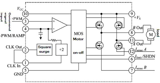
Overheat and programmable Current-limiting protection |
|
Absolute maximum rating |
Recommended operating conditions |
|
Supply voltage+VS:200V Supply voltage+VCC:16V Input voltage,+PWM:0~+11V Internal power loss:250W Storage temperature:-55~+125℃ operating temperature(TC):-40~+85℃ |
Supply voltage+VS:120V Supply voltage+VCC:15V Input voltage,+PWM:+3~+7V Shut-off input voltage,Ilimit/SHDN:0.1V |
|
No |
Character |
Conditions -55℃≤Tc≤125℃ |
HSA12 |
Symbol |
||
|
Min |
Typical value |
Max |
||||
|
1 |
Clock output high level |
- |
4.8 |
- |
5.3 |
V |
|
2 |
Clock output low level |
- |
0 |
- |
0.4 |
V |
|
3 |
Clock output frequency |
- |
392 |
400 |
408 |
kHZ |
|
4 |
Triangular center voltage |
- |
- |
5 |
- |
V |
|
5 |
Triangular wave peak -peak voltage |
- |
- |
4 |
- |
V |
|
6 |
Continuous working current |
- |
- |
15 |
- |
A |
|
7 |
Power +Vs |
- |
16 |
120 |
200 |
V |
|
8 |
Power +VCC |
- |
14 |
15 |
16 |
V |
|
9 |
+VCCstatic current |
IO=0 |
- |
- |
150 |
mA |
|
10 |
Ilimit/shutoff threshold |
- |
90 |
- |
110 |
mV |

|
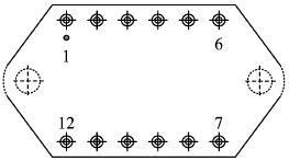
No |
symbol |
Designation |
No |
symbol |
Designation |
|
1 |
CLK In |
Clock input |
7 |
Isense B |
Current sensing output B |
|
2 |
CLK Out |
Clock output |
8 |
Bout |
Output B |
|
3 |
+PWM |
+PWM input signal |
9 |
+VS |
+VS input |
|
4 |
-PWM/RAMP |
Internal triangular output |
10 |
+VCC |
+Vcc input |
|
5 |
GND |
System Ground |
11 |
Aout |
Output A |
|
6 |
Ilimit/SHDN |
current limiter/ shut off input |
12 |
Isense A |
Current sensing output A |


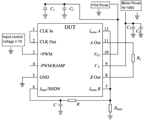
7.1 Power supply bypass
HSA12 power supply should have plenty of bypass to ensure its correct operation, the motor power supply should add a ceramic capacitor C3, and then in parallel with a low ESR value of the bypass capacitor C4, the capacitance should be at least 10uF/ A .for VCC the same , a 0.1 μF-0.47μF / 50V ceramic capacitor C1 and a low ESR value of 6.8μF-10μF/50V bypass capacitor C2. All bypass capacitors should be connected as close as possible to the corresponding root of power port.

|
Symbol |
Data/mm |
||
|
|
Min |
Typical |
Min |
|
A |
- |
- |
6.99 |
|
A1 |
2.28 |
- |
2.44 |
|
Φb |
1.47 |
- |
1.57 |
|
D |
- |
- |
40.40 |
|
E |
- |
- |
40.40 |
|
e |
- |
5.08 |
- |
|
e1 |
- |
30.48 |
- |
|
L |
11.43 |
- |
12.70 |
|
X1 |
49.56 |
- |
49.96 |
|
X |
- |
- |
58.90 |
|
ΦP |
3.80 |
- |
4.20 |
 X
X