|
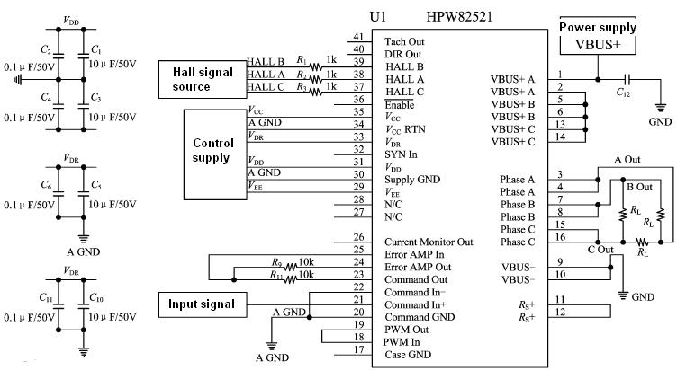
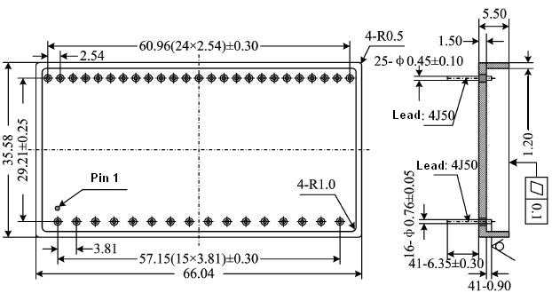
Replace HPW82521 series of DDC Company |
|
|
1A, 3A, 10A continuous output current |
|
|
200V motor supply voltage |
|
|
Torque control with four quadrants |
|
|
60/120 phase selection |
|
|
10KHZ~100KHZ operating frequency |
|
No |
Character |
(Unless other wise, VDR=15V±1% VCC=5V±0.5%, VDD=5V±0.5% VEE=-(5V±5%) VS=56V±3V,ENABLE=0 Input triple Hall TTL square wave signal 40Hz:-55℃≤Tc≤125℃) |
HPW-82521N |
Unit |
||
|
Group |
Min |
Max |
||||
|
1 |
Control supply VDR Static current/IDR |
No load |
1、2、3 |
- |
40 |
mA |
|
2 |
Control supply VDD Static current /IDD |
No load |
1、2、3 |
- |
50 |
mA |
|
3 |
Control supply VEE Static current /IEE |
No load |
1、2、3 |
- |
50 |
mA |
|
4 |
Bias current/IOFFSET |
No load |
1 |
-300 |
+300 |
mA |
|
5 |
Speed signal low level/VOL |
RL=18Ω±2Ω(△connect) |
1 |
0.7 |
1.2 |
V |
|
6 |
Working frequency /fcp |
RL=18Ω±2Ω(△ connect ) |
4 |
10 |
55 |
KHZ |
|
7 |
PWM Positive peak voltage/Vp+ |
No load |
1 |
2.3 |
2.8 |
A |
|
8 |
PWM Negative peak voltage /Vp- |
No load |
1 |
-2.5 |
-2.3 |
mA |
|
9 |
Duty cycle/D |
No load |
1 |
49 |
51 |
% |

|
No |
symbol |
Designation |
No |
symbol |
Designation |
|
|
1 |
VBUS+A |
A channel Power supply |
23 |
COMMAND OUT |
Current control signal output |
|
|
2 |
VBUS+A |
A channel Power supply |
24 |
ERROR AMP OUT |
Error amplifier output |
|
|
3 |
PHASE A |
A channel Output |
25 |
ERROR AMP IN |
Error amplifier input |
|
|
4 |
PHASE A |
A channel Output |
26 |
CMO |
Current monitor output |
|
|
5 |
VBUS+B |
B channel Power supply |
27 |
N/C |
N/C |
|
|
6 |
VBUS+B |
B channel Power supply |
28 |
N/C |
N/C |
|
|
7 |
PHASE B |
B channel Output |
29 |
VEE |
VEE power |
|
|
8 |
PHASE B |
B channel Output |
30 |
Supply GND |
Control ground |
|
|
9 |
VBUS- |
Power supply Ground |
31 |
VDD |
VEE power |
|
|
10 |
VBUS- |
Power supply Ground |
32 |
SYNC IN |
Synchronize input |
|
|
11 |
RS+ |
Current sampling |
33 |
VDR |
VDR power |
|
|
12 |
RS+ |
Current sampling |
34 |
VCC RTN |
VCC power ground |
|
|
13 |
VBUS+C |
C channel Power supply |
35 |
VCC |
VCC |
|
|
14 |
VBUS+C |
C channel Power supply |
36 |
ENABLE |
Enable |
|
|
15 |
PHASE C |
C channel Output |
37 |
HALL C |
Hall signal C |
|
|
16 |
PHASE C |
C channel Output |
38 |
HALL A |
Hall signal A |
|
|
17 |
CASE GND |
Case ground |
39 |
HALL B |
Hall signal B |
|
|
18 |
PWM IN |
PWM Input |
40 |
DIR OUT |
Direction out |
|
|
19 |
PWM OUT |
PWM Output |
41 |
TACH OUT |
Count output |
|
|
20 |
COMMAND GND |
Current control signal ground |
|
|
|
|
|
21 |
COMMAND IN+ |
Positive current control signal |
|
|
|
|
|
22 |
COMMAND IN- |
Negative current control signal |
|
|
|
|


 X
X