4.8W High reliability Point of Load DC to DC Converters (POL)

Sales 4.8W High reliability Point of Load DC to DC Converters (POL)

  • Output Voltage (V) : 7V-18V
  • Input DC Voltage (V) : 7V-18V
  • Max. Output Power (W) : 4.8W

Product Detail  

1 Features of MNSX12N0R4S High Reliability Point of Load DC/DC Converters (POL)

Input DC Voltage range(Continuous):7~18V


Typical input DC voltage:12V

Output voltage:-12V

Output power:4.8W

Temperature(Tc):-40~85℃

BOOST topological structure, PWM Control

2. Scope of application of MNSX12N0R4S High Reliability Point of Load DC to DC Converters (POL)

MNSX12N0R4S DC to DC Converter is used in aerospace high reliable electronic system.

3. Descriptions of MNSX12N0R4S High Reliability Point of Load DC to DC Converters (POL)

MNSX12N0R4S point of load DC/DC converter uses BUCK-BOOST topological structure. Circuit contains input filter, PWM control, and reactive circuit and so on. Circuit also has protected function for over-current and under-voltage to improve the reliability.
The MNSX12N0R4S point of load DC/DC converter is modular circuit structure; it’s used by PCB surface assembly process, no embedment, package is used by 2014 mucilage glue, gushing three proofing, and copper shell.

4. Technical Specifications of MNSX12N0R4S High Reliability Point of Load DC  DC Converters (POL)

Form 2   Rated condition and recommended condition

Absolute max rating

Recommended condition

Input voltage:18V

Output power:4.8W

Storage temperature:-45~105℃

Leads resistance welding temperature(10s):< 300℃

Junction temperature:< 150℃

Input voltage:7~18V

working temperature  range(Tc):-40~85℃


Form 3 Electrical Characteristic

No.

Characteristic

Symbol

Conditions

(otherwise specified,-40℃≤Tc≤85℃,VIN=12V±0.5V)

Limit value

Unit

min

max

1

Input voltage

Vo

VI=7V-18V,Io=0.05A-0.4A

-12.15

-11.85

V

2

Output current

Io

VI=7V-18V

0.05

0.4

A

3

Output ripple voltage(peak-peak)

VP-P

TA=25℃,BW≤20MHz, full load

-

120

mV

4

Voltage regulation rate

Sv

full load,VI=7V 18V

-

0.5

%

5

Load regulation rate

SI

Io=0.05A 0.4A

-

1

%

6

Efficiency

η

TA=25℃, full load

75

-

%

Output in parallel capacitance with 0~10μF.


5. Circuit block diagram of MNSX12N0R4S High Reliability Point of Load DC  DC Converter (POL)


Fig 2    Product elementary diagram

6. Typical characteristic curve of MNSX12N0R4SHigh Reliability Point of Load DC  DC Converter (POL)


Fig  3  Efficiency(output power)


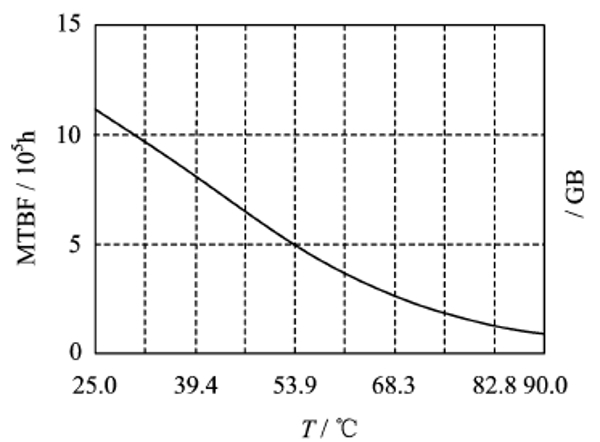
7. MTBF curve of MNSX12N0R4S High Reliability Point of Load DC-DC Converter (POL)


Char 4  MTBF Temperature Curve
(Prediction is based on well grounded )

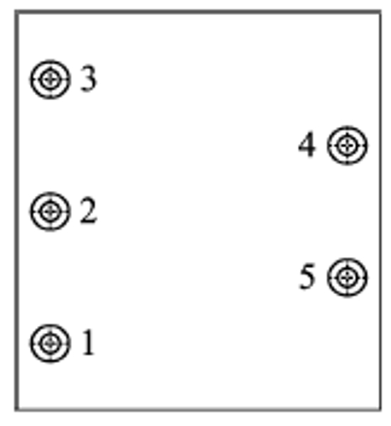
8. Pin Designation of MNSX12N0R4S High Reliability Point of Load DC-DC Converter (POL)


Fig  5 Upward view

Form 4 Pin Designation

No.


Symbol

Function

1

VI

Inputpositive

2

Vo

Output -12V

3

GND

Input Output common

4

GNDC

Package common

5

GNDC

Package common


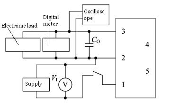
9. Typical Connection Diagram of MNSX12N0R4S High Reliability Point of Load DC-DC Converter (POL)


Fig  6  Electrical testing wiring diagram

10.Package Specifications of MNSX12N0R4S High Reliability Point of Load DC-DC Converter (POL)


Fig  7 package outline drawing(upward view)

Form 5  Package Outline

Symbol

Data/mm

Min

Typical

Min

A

-

-

22.86

B

-

-

23.87

C

-

-

7.87

Ψd

0.47

-

0.73

e1

-

2.54

-

e2

-

5.08

-

e3

-

11.4

-

e4

-

25.4

-

F1

1.0

-

1.6

F1

0.1

-

0.7

L1

3.55

-

-

L2

1.15

-

1.75

Note: Size for a e1 e2 e3 e4 is guaranteed by manufacturing of packages, do not have inspection requirements.

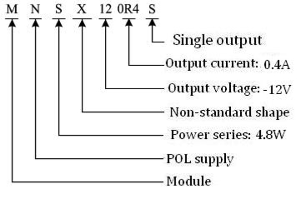
11. Ordering Information of MNSX12N0R4S High Reliability Point of Load DC-DC Converter (POL)


Fig  8 Ordering Information


Application Notes:


  • The influence of external disturbance on the test accuracy should be avoided.
  • The voltage detection point should be kept at the root of the pin of the testing product.
  • Do not plug the product with electricity.
  • Before power the testing product, you must confirm the polarity of the power supply to avoid damaging products by misconnection. At the same time, please ensure that the power supply voltage and load current does not exceed using limitation of the testing product.
  • When using the shell temperature can not exceed the specified temperature, or to increase the use of heat sink.
  • When ordering this device,the detailed electrical specifications shall be based on relevant standards.
Leave A Message
If you are interested in our products and want to know more details,please leave a message here,we will reply you as soon as we can.
X

Home

Supplier

Leave a message

Leave a message

If you are interested in our products and want to know more details,please leave a message here,we will reply you as soon as we can.