High-reliability electronic system for aviation and aerospace, weapon and ships etc.
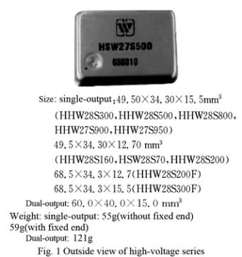
This series products are high reliable hybrid thick film large power DC-DC converter. By using half-bridge circuit topology and pulse width modulation principle, the output sampling voltage isolated by optocoupler to modulate the pulse width and form the closed-loop control to make the product a stable voltage output. This series products are made by thick film hybrid integrated process, hermetically sealed metal cases. Product design and manufacturing meets MIL-PRF-38534 requirements. Customers can connect the matching power EMI filters in the input port to improve the product’s electromagnetic compatibility.
Tabel2 Rated conditions and recommended operating conditions
|
Absolute Max. Rated value |
|
|
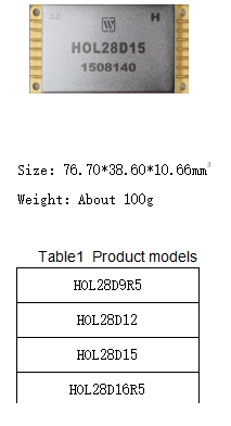
Output voltage:15.5V~41V Output power:150W Storage temperature:-65℃~150℃ |
Mechanical Shock:1500g Lead resistance to welding temperature:300℃(15s) Weight:100g ESD:2000V |
Table 3-1 Electric characteristics
|
No. |
Parameter |
Conditions (Unless other wise,-55℃≤Tc≤125℃,VIN=28V±5%) |
HOL28D9R5 |
HOL28D12 |
HOL28D15 |
||||||
|
Min |
Max |
Min |
Max |
Min |
Max |
||||||
|
1 |
Input voltage/V |
Low、High、Ambient Temperature |
16 |
40 |
16 |
40 |
16 |
40 |
|||
|
2 |
Output voltage/V |
Positive |
Ambient, Full load |
9.31 |
9.69 |
11.80 |
12.2 |
14.70 |
15.30 |
||
|
Negative |
-9.69 |
-9.31 |
-12.20 |
-11.80 |
-15.30 |
-14.70 |
|||||
|
Positive |
Low/high, Full load |
9.31 |
9.69 |
11.80 |
12.20 |
14.70 |
15.30 |
||||
|
Negative |
-9.69 |
-9.31 |
-12.20 |
-11.80 |
-15.30 |
-14.70 |
|||||
|
3 |
Output current/A |
VIN=15V~50V |
― |
6.3 |
― |
5 |
― |
5 |
|||
|
4 |
Output Power/W |
|
― |
120 |
― |
120 |
― |
150 |
|||
|
5 |
Output Ripple Voltage/mV |
BW≤20MHz,Full load |
― |
100 |
― |
120 |
― |
150 |
|||
|
6 |
Line Regulation/mV |
Positive |
VIN=16V~40V,Full load |
― |
95 |
― |
120 |
― |
150 |
||
|
Negative |
― |
95 |
― |
120 |
― |
150 |
|||||
|
7 |
Load Regulation/mV |
Positive |
No load to full |
― |
95 |
― |
120 |
― |
150 |
||
|
Negative |
― |
95 |
― |
120 |
― |
150 |
|||||
|
8 |
Input current/mA |
Inhibited |
― |
10 |
― |
10 |
― |
10 |
|||
|
Io=no load |
― |
100 |
― |
100 |
― |
100 |
|||||
|
9 |
Input Ripple current/mA |
BW≤20MHz,Full load |
― |
200 |
― |
200 |
― |
200 |
|||
|
10 |
Efficiency/% |
Full load |
Ambient |
89 |
- |
88 |
― |
90 |
― |
||
|
Low/high |
86 |
― |
86 |
― |
86 |
― |
|||||
|
11 |
Isolation/MΩ |
Input to output or any pin to case at 500V,Tc=25℃ |
100 |
― |
100 |
― |
100 |
― |
|||
|
12 |
Inhibit voltage |
|
― |
0.3 |
― |
0.3 |
― |
0.3 |
|||
|
13 |
Inhibit open circuit voltage/V |
Full load |
1.25 |
4 |
1.25 |
4 |
1.25 |
4 |
|||
|
14 |
Under voltage turn-on voltage/V |
Full load |
14.5 |
15.5 |
14.5 |
15.5 |
14.5 |
15.5 |
|||
|
15 |
Under voltage cut-off voltage/V |
Full load |
14 |
15 |
14 |
15 |
14 |
15 |
|||
|
16 |
Short Circuit Protection power consumption |
|
- |
15 |
- |
15 |
- |
15 |
|||
|
17 |
load/μF |
Tc=25℃ |
― |
500 |
― |
500 |
― |
500 |
|||
|
18 |
Full load |
250 |
350 |
250 |
350 |
250 |
350 |
||||
|
19 |
Cross regulation/mV |
One side 30% load, the other from 30% to 70% load |
― |
380 |
― |
480 |
― |
600 |
|||
|
20 |
Step Load Response Transient(mV pK) |
50%load→full load or Full load →50% load |
― |
800 |
― |
800 |
― |
800 |
|||
|
21 |
Step Load Response Recovery(μs) |
50%load→full load or Full load →50% load |
― |
800 |
― |
600 |
― |
600 |
|||
|
22 |
Step Line Response Transient(mV pK) |
VIN:16V→40V, VIN:40V→16V,Io=Full load |
― |
1200 |
― |
1200 |
― |
1200 |
|||
|
23 |
Step Line Response Recovery(μs) |
VIN:16V→40V, VIN:40V→16V,Io=Full load |
― |
1500 |
― |
1500 |
― |
1500 |
|||
|
24 |
Start-up Overshoot(mV pK) |
VIN:0→28V, Io=Full load |
― |
25 |
― |
25 |
― |
25 |
|||
|
25 |
Start-up Delay (ms) |
VIN:0→28V, Io=Full load |
― |
30 |
― |
20 |
― |
20 |
|||
Table 3-2 Electric characteristics
|
No. |
Parameter |
Conditions (Unless other wise,-55℃≤Tc≤125℃,VIN=28V±5%) |
HOL28D16R5 |
HOL28DXX |
HOL28DXX |
|||||||||||
|
Min |
Max |
Min |
Max |
Min |
Max |
|||||||||||
|
1 |
Input voltage/V |
Low、High、Ambient Temperature |
20 |
36 |
|
|
|
|
||||||||
|
2 |
Output voltage/V |
Positive |
16.25 -16.75 |
16.25 |
16.25 |
|
|
|
|
|||||||
|
Negative |
-16.75 |
-16.75 |
|
|
|
|
||||||||||
|
Positive |
16.25 -16.75 |
16.25 |
16.25 |
|
|
|
|
|||||||||
|
Negative |
-16.75 |
-16.75 |
|
|
|
|
||||||||||
|
3 |
Output current/A |
|
― |
3.5 |
|
|
|
|
||||||||
|
4 |
Output Power/W |
|
― |
115 |
|
|
|
|
||||||||
|
5 |
Output Ripple Voltage/mV |
BW≤20MHz,Full load |
― |
150 |
|
|
|
|
||||||||
|
6 |
Line Regulation/mV |
Positive |
VIN=16V~40V,Full load |
― |
165 |
|
|
|
|
|||||||
|
Negative |
― |
165 |
|
|
|
|
||||||||||
|
7 |
Lode Regulation/mV |
Positive |
No load to full |
― |
165 |
|
|
|
|
|||||||
|
Negative |
― |
165 |
|
|
|
|
||||||||||
|
8 |
Input current/mA |
Inhibited |
― |
10 |
|
|
|
|
||||||||
|
Io=no load |
― |
100 |
|
|
|
|
||||||||||
|
9 |
Input Ripple current/mA |
BW≤20MHz,Full load |
― |
200 |
|
|
|
|
||||||||
|
10 |
Efficiency/% |
Full load |
|
87 |
- |
|
|
|
|
|||||||
|
|
86 |
- |
|
|
|
|
||||||||||
|
11 |
Isolation/MΩ |
Input to output or any pin to case at 500V,Tc=25℃ |
100 |
- |
|
|
|
|
||||||||
|
12 |
Inhibit voltage |
|
0 |
0.7 |
|
|
|
|
||||||||
|
13 |
Inhibit open circuit voltage/V |
Full load |
1.25 |
4.0 |
|
|
|
|
||||||||
|
14 |
Under voltage open voltage/V |
Full load |
18 |
19.5 |
|
|
|
|
||||||||
|
15 |
Under voltage cut-off voltage/V |
Full load |
17 |
19 |
|
|
|
|
||||||||
|
16 |
Short Circuit Protection |
|
― |
15 |
|
|
|
|
||||||||
|
17 |
load/μF |
Tc=25℃ |
― |
330 |
|
|
|
|
||||||||
|
18 |
Full load |
250 |
350 |
|
|
|
|
|||||||||
|
19 |
Cross regulation/mV |
One side 30% load, the other from 30% to 70% load |
― |
800 |
|
|
|
|
||||||||
|
20 |
Step Load Response Transient(mV pK) |
50%load→full load or Full load →50% load |
― |
800 |
|
|
|
|
||||||||
|
21 |
Step Load Response Recovery(μs) |
50%load→full load or Full load →50% load |
― |
600 |
|
|
|
|
||||||||
|
22 |
Step Line Response Transient(mV pK) |
VIN:16V→40V, VIN:40V→16V,Io=Full load |
― |
1200 |
|
|
|
|
||||||||
|
23 |
Step Line Response Recovery(μs) |
VIN:16V→40V, VIN:40V→16V,Io=Full load |
― |
1500 |
|
|
|
|
||||||||
|
24 |
Start-up Overshoot(mV pK) |
VIN:0→28V, Io=Full load |
― |
150 |
|
|
|
|
||||||||
|
25 |
Start-up Delay (ms) |
VIN:0→28V, Io=Full load |
― |
50 |
|
|
|
|
||||||||
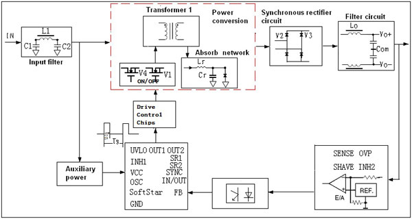
Fig 1 HOL28D Series circuit block diagram
6. Typical Performance Curves of HOL28D Series Thick Film DC to DC Converter(Testing condition as per Tc=25℃,VIN=28V±5%, Full load, unless otherwise specified)
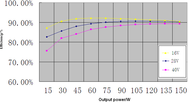
Fig 2 HOL28D15 Efficiency curves
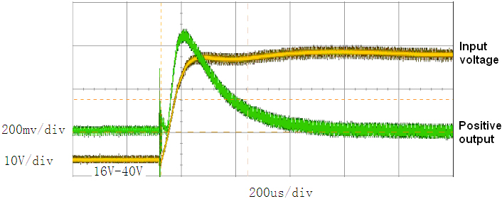
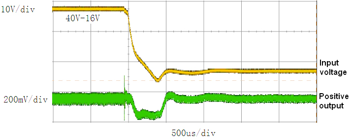
Fig 3 HOL28D15Input Step Curve
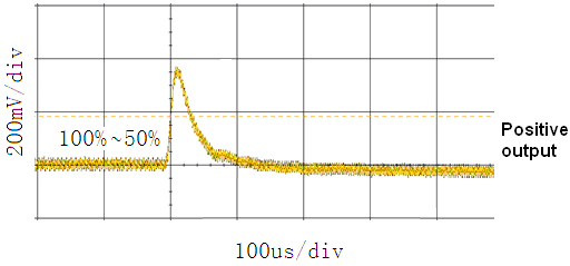
Fig 4 HOL28D15 Step Load Response(Positive output)
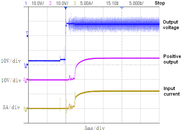
Fig 5 HOL28D15 Start-up Overshoot/Start-up Delay
(Well ground condition)
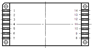
Fig 7 Pin Out Bottom View
Pin Designation
|
Pin |
Symbol |
Designation |
Pin |
Symbol |
Designation |
|
1 |
VIN |
Positive input |
8 |
Vo+ |
Positive output |
|
2 |
GNDI |
Input ground |
9 |
COM |
Common |
|
3 |
NC |
NC |
10 |
Vo- |
Negative output |
|
4 |
INH1 |
Primary Inhibit |
11 |
Trim |
Trimming |
|
5 |
NC |
NC |
12 |
SHARE |
Current flow control terminal |
|
6 |
SYNI |
Synchronous input |
13 |
NC |
NC |
|
7 |
NC |
NC |
14 |
NC |
NC |
Notes:HOL28D15、HOL28D16R5(This two models using this package type)
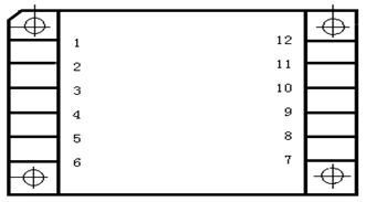
Fig 8 Pin out Bottom View
Pin Designation
|
Pin |
Symbol |
Designation |
Pin |
Symbol |
Designation |
|
1 |
VIN |
Positive input |
7 |
Vo+ |
Positive output |
|
2 |
GNDI |
Input ground |
8 |
COM |
Common |
|
3 |
NC |
NC |
9 |
Vo- |
Negative output |
|
4 |
INH1 |
Primary Inhibit |
10 |
Trim |
Trimming |
|
5 |
NC |
NC |
11 |
SHARE |
Current flow control terminal |
|
6 |
SYNI |
Synchronous input |
12 |
NC |
NC |
Notes: Subsequent series of products designed in the form of the package
9. Typical Connection Diagram of HOL28D Series Thick Film DC DC Converter
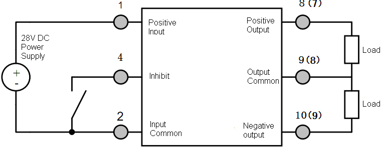
Fig 9 Products Using Connection Diagram
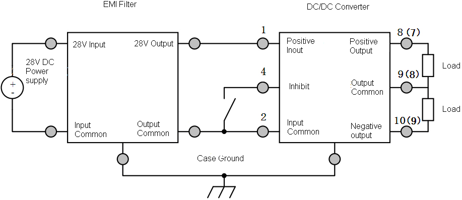
Fig 10 EMI Filter Connection Diagram
10 Package Specifications of HOL28D Series Thick Film DC DC Converter
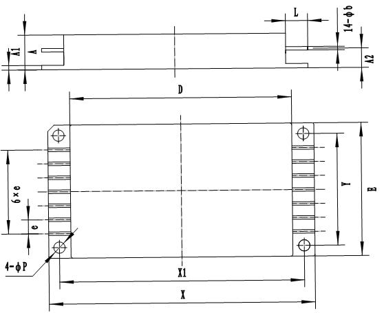
Fig 11 Bottom View
Table 4 Package Outline
|
Dimension Symbols |
Unit/mm |
||
|
Minimum |
Nominal |
Maximum |
|
|
A |
- |
- |
10.66 |
|
A1 |
0.97 |
|
1.57 |
|
A2 |
5.29 |
|
5.89 |
|
φb |
0.87 |
|
1.13 |
|
D |
- |
- |
64.00 |
|
E |
- |
- |
38.60 |
|
e |
- |
4.00 |
- |
|
L |
5.35 |
- |
- |
|
φP |
3.00 |
- |
3.60 |
|
Y |
31.50 |
- |
32.50 |
|
X1 |
69.60 |
- |
70.60 |
|
X |
- |
- |
76.70 |
|
Notes: e is interchangeable size, made by the shell manufacturing and inspection, this specification does not do the assessment requirements. |
|||
Table 5 Case Materials
|
Case Model |
Header |
Header Plating |
Cover |
Cover Plating |
Pin |
Pin Plating |
Sealing Style |
Notes |
|
fpp6438-14d |
Cold Rolled Steel(10#) |
Dau-2/Ni4Au1.0 |
Kovar (4J42) |
Ni |
Oxygen-free copper |
|
Parallel seam welding |
|

Fig 12 Bottom View
Table 6 Package Outline
|
Dimension Symbols |
Unit/mm |
||
|
Minimum |
Nominal |
Maximum |
|
|
A |
- |
- |
10.66 |
|
A1 |
5.29 |
|
5.89 |
|
φb |
0.87 |
|
1.13 |
|
D |
- |
- |
76.70 |
|
E |
- |
- |
38.60 |
|
e |
- |
5.08 |
- |
|
L |
5.35 |
- |
- |
|
φP |
3.00 |
- |
3.60 |
|
X1 |
69.90 |
70.1 |
70.3 |
|
X2 |
- |
- |
64.00 |
|
Y1 |
31.80 |
32 |
32.20 |
|
Notes:e is interchangeable size, made by the shell manufacturing and inspection, this specification does not do the assessment requirements. |
|||
Table 7 Package Outline
|
Case Model |
Header |
Header Plating |
Cover |
Cover Plating |
Pin |
Pin Plating |
Sealing Style |
Notes |
|
fpp6438-12d |
Cold Rolled Steel(10#) |
Dau-2/Ni4Au1.0 |
Kovar (4J42) |
Ni |
Oxygen-free copper |
|
Parallel seam welding |
|
11. Ordering information of HOL28D Series Thick Film Hybrid Large Power DC-DC Converter
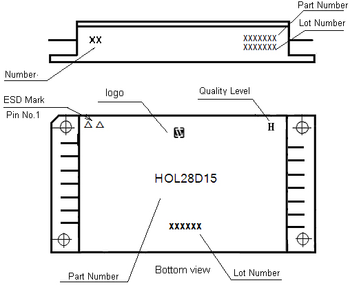
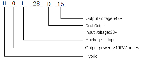
Fig 13 Part Numbering Key
Application Notes

Subscribe to our weekly newsletter and receive exclusive offers on products you love!
 X
X


 Gold Supplier