♦Pulse mode: monopulse/double-pulse
♦Signal level: 3.3-24V compatible; serial resistance not necessary for the application of PLC.
♦Power voltage: 24-100V DC or 18-80V AC, 75V AC recommended
DS86 digital display stepper servo driver
Based on the new 32-bit DSP platform, provided with vector control technology and servo demodulation function internally, DS86 stepper servo driver enables the stepper servo system to feature low noise, low heating.DS86 is used to drive two-phase closed-loop stepper motors base below 86mm.
Typical applications: welding machine, wire-stripping machine, labeling machine,carving machine, electronic assembly equipment etc.
Product Specification
| Drive features | Operating instructions | ||||||
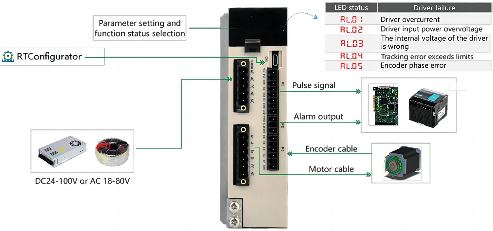
| Signal interface | PUL+and PUL-for the positive and negative ends of the control pulse signal;DIR+and DIR-for the positive and negative end of the direction signal;ENA is the enable signal;IN2 is undefined,COM+is the common correct,COM-is the common negative;BRK-is the brake output signal,ALM-is the alarm output signal;PEND-for the position output signal. | ||||||
| Encoder interface | EB+and EB-are the encoder B direction signals;EA+and EA-are encoder A direction signals;VCC and GND are the encoder power interfaces | ||||||
| Motor interface | A+,A-,B+,B-are stepper servo motor winding interfaces,need to be connected with the motor identification color,can not be exchanged.PE grounding wire,NC suspended not connected. | ||||||
| Power port | AC and AC are common input terminals for AC and DC power supplies.DS86 operating voltage range is 18-80VAC or 24-100VDC,power supply is greater than 200W.PE ground cable,NC suspended without connection | ||||||
The parameters of the drive can be set from PA-00 to PA-40
| Steps/revolutions | Parameter names | Scope | Default values |
Instructions |
| 00 | Control mode | [0,2] | 1 | 0:open loop operation 1:servo mode 1 2:Servo Mode two |
| 01 | Subdiyision | [200,65535] | 1600 | The number of pulses required for the motor to run one turn |
| 02 | Maximum current | [100,7000] | 7000 | When matching different motors,first confirm whether the maximum current is appropriate before connecting the motor |
| 03 | Percentage of Base current | [1,100] | 50 | |
| 04 | Encoder resolution | [500,65535] | 4000 | The resolution of a 1000-wire encoder is 4000 |
| 05 | Position error alarm threshold | [100,65535] | 4000 | Set the drive tracking error alarm threshold |
| 06 | Reverse direction | [0,1] | 0 | 0:Default direction 1:The motor running direction is reversed |
| 07 | Instruction filtering | [1,512] | 128 | Time lag =set point x 50us,parameter set to 1 when interpolating motion |
| 08 | Pulse Mode | [0,1] | 0 | 0:Pulse+direction 1:Double pulse |
| 09 | Pulse effective edge | [1,512] | 128 | 0:Rising edge effective 1:The falling edge is effectiv |
| 10 | Enable level | [0,1] | 0 | 0:Normally open 1:Normally closed |
DS86 Connections
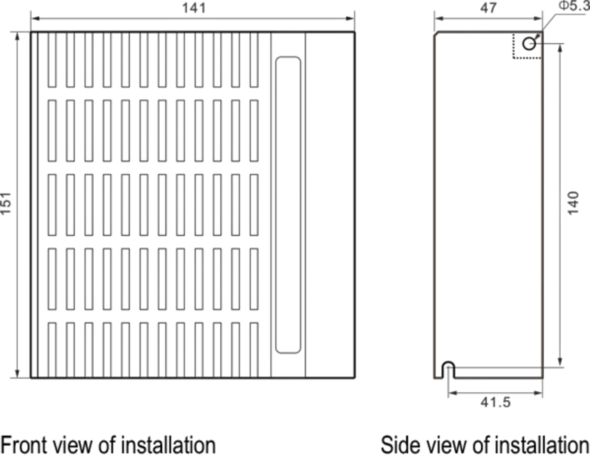
Product Dimensions
| Common problems and countermeasures | ||||
| Phenomena | Possible situation | Solutions | ||
| Motor not turning | The power light does not work | Check the power supply circuit for normal power supply | ||
| The motor locks the shaft but does not turn | The pulse signal is weak and the signal current is increased to 7-16mA | |||
| Too little speed | Pick the right subdivision | |||
| Drive protected | Power back on | |||
| Enable the signal problem | Pull the enable signal high or not | |||
| Incorrect command pulse | Check the upper computer for pulse output | |||
| Motor steering error | Motor steering in reverse | Change the motor wiring sequence or adjust the direction of instructions | ||
| There is a break in the motor line | Check the wires for poor contact | |||
| The motor has only one direction | Pulse mode is wrong or DIR port is damaged | |||
| Alarm indicator light | Motor wire is incorrectly connected | Check the wiring | ||
| Voltage is too high or too low | Check the power supply | |||
| Damaged motor or drive | Replace the motor or drive | |||
| Wrong location or speed | Signal interference | Eliminate interference and ground reliably | ||
| Incorrect command input | Check the upper computer instructions to ensure the correct output | |||
| The pulse per revolution is set incorrectly |
Check dip switch status and connect correctly | |||
| Motor drop ster | Check whether the command speed is too large and the motor selection is small | |||
| The driver terminal is burned out |
Short circuit between terminals | Check the power supply polarity or external short circuit | ||
| There is too much internal resistance between terminals |
Check whether excess solder has been added to the wire and wire connection to form tin clumps |
|||
| Motor gridlock | The acceleration and deceleration time is too short |
Reduce the command acceleration or increase the driver filter parameter | ||
| Too little motor torque | Choose a high-torque motor | |||
| Heavy load | Check the weight and quality of the load and adjust the mechanical structure | |||
| Too little current | Check the dip switch to increase the drive output current | |||
FAQ
Can we accept samples customized?
No problem for samples order, and welcome your testing before your big order.
OEM and ODM are available?
Yes, we accept customized products
Can I get a lower price if I order large quantities?
Yes, Cheaper prices with bigger size orders, please contact us and we will give you a quatation.

Subscribe to our weekly newsletter and receive exclusive offers on products you love!
 X
X


 Gold Supplier


