|
ABSOLUTE MAXIMUM RATINGS |
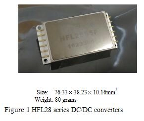
MODELS |
|
|
• Input Voltage: 16 to 40 VDC |
SINGLE |
DUAL |
|
• Power Dissipation: 65 watts |
HFL28S5 |
HFL28D5 |
|
• Lead Soldering Temperature:300℃(10s) |
HFL28S12 |
HFL28D12 |
|
• Storage Temperature Range: -55℃ to +125℃ |
HFL28S15 |
HFL28D15 |
|
• Inhibit Voltage: 0.2V max |
HFL28S28 |
|
|
• External Synchronous Signals: Frequency Range: 400k to 600kHz Duty Ratio: 40% to 60% Level: 0.8 V≤V≤5V |
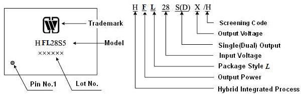
Table 1 Product models | |
| Single output models | HFL28S5 | HFL28S12 | ||||
| Parameter | Conditions | Min | Max | Min | Max | |
| Output Voltage(V) | Io=full load | Ambient temperature | 4.95 | 5.05 | 11.88 | 12.12 |
| high and low temperature | 4.875 | 5.125 | 11.76 | 12.24 | ||
| Output Current(A) | Vin = 16 TO 40 VDC | — | 10 | — | 5 | |
| Output Power(W) | — | — | 50 | — | 60 | |
|
Output Ripple Voltage (mV) |
BW=10 kHz to 2 MHz Io=full load |
Ambient temperature | — | 35 | — | 75 |
| high and low temperature | — | 50 | — | 100 | ||
| Line Regulation(mV) | Vin = 16 TO 40 VDC,Io=full load | — | 20 | — | 20 | |
| Load Regulation(mV) | Io=No load to load | — | 20 | — | 20 | |
|
Input Ripple Current (mA) |
BW=10 kHz to 10 MHz Io=full load |
Ambient temperature | — | 45 | — | 45 |
| high and low temperature | — | 50 | — | 50 | ||
| Efficiency (%) | Io=full load | Ambient temperature | 77 | — | 83 | — |
| high and low temperature | 75 | — | 81 | — | ||
| Isolation (MΩ) | Input to output or any pin to case (except case ground pin) at 500 VDC, TA = 25° C | 100 | — | 100 | — | |
| Inhibit Function | TA = 25° C,Inhibit voltage, output disabled | 0 | 0.2 | 0 | 0.2 | |
| Protection Function | TA = 25° C | 5 | — | 5 | — | |
| Start-up Overshoot(mV pk) | Vin=0 to 28V, Io=full load | — | 25 | — | 50 | |
| Start-up Delay(ms) | Vin=0 to 28V, Io=full load | — | 6 | — | 6 | |
| Capacitive Load(μF) | TA = 25° C, No effect on DC performance | — | 1000 | — | 1000 | |
| Switching Frequency(kHz) | Io=full load | 400 | 600 | 400 | 600 | |
| Step Load Response Transient (mV pK) | 50% load -- full load -50% load | -350 | 350 | — | 600 | |
| Step Load Response | 50% load -- full load -50% load | — | 3000 | — | 3000 | |
| Recovery (µs) | ||||||
| Step Line Response Transient (mV pK) | Vin=16~40V, Io=full load, | — | 300 | — | 400 | |
| Vin=40~16V, Io=full load | ||||||
| Step Line Response Recovery (µs ) | Vin=16~40V, Io=full load, | — | 300 | — | 300 | |
| Vin=40~16V, Io=full load | ||||||
|
Load Fault recovery (ms) |
IO:short circuit to full load | — | 4 | — | 4 | |
|
Single output models |
HFL28S15 |
HFL28S28 |
||||
|
Parameter |
Conditions |
Min |
Max |
Min |
Max |
|
|
Output Voltage (V) |
Io=full load |
Ambient temperature high and low temperature |
14.85 14.55 |
15.15 15.45 |
27.72 27.16 |
28.28 28.84 |
|
Output Current(A) |
Vin= 16 TO 40 VDC |
— |
4.33 |
— |
2.32 |
|
|
Output Power(W) |
— |
— |
65 |
— |
65 |
|
|
Output Ripple Voltage(mV) |
BW=10 kHz to 2 MHz Io=full load |
Ambient temperature
high and low temperature |
—
— |
85
110 |
—
— |
200
300 |
|
Line Regulation(mV) |
Vin = 16 TO 40 VDC,Io=full load |
— |
20 |
— |
120 |
|
|
Load Regulation(mV) |
Io=No load to load |
— |
20 |
— |
150 |
|
|
Input Ripple Current (mA) |
BW=10 kHz to 10 MHz Io=full load |
Ambient temperature high and low temperature |
— — |
45 50 |
— — |
50 60 |
|
Efficiency (%) |
Io=full load |
Ambient temperature high and low temperature |
84 82 |
— — |
83 79 |
— — |
|
Isolation (MΩ) |
Input to output or any pin to case (except case ground pin) at 500 VDC, TA = 25°C |
100 |
— |
100 |
— |
|
|
Inhibit Function |
TA = 25°C,Inhibit voltage, output disabled |
0 |
0.2 |
0 |
0.2 |
|
|
Protection Function |
TA = 25°C |
5 |
— |
5 |
— |
|
|
Start-up Overshoot (mV pk) |
Vin=0 to 28V, Io=full load |
— |
50 |
— |
100 |
|
|
Start-up Delay(ms) |
Vin=0 to 28V, Io=full load |
— |
6 |
— |
6 |
|
|
Capacitive Load(μF) |
TA = 25°C, No effect on DC performance |
— |
1000 |
— |
500 |
|
|
Switching Frequency(kHz) |
Io=full load |
400 |
600 |
400 |
600 |
|
|
Step Load Response Transient (mV pK) |
50% load -- full load -50% load |
— |
600 |
— |
1400 |
|
|
Step Load Response Recovery (µs) |
50% load -- full load -50% load |
— |
3000 |
— |
3000 |
|
|
Step Line Response Transient (mV pK) |
Vin=16~40V, Io=full load, Vin=40~16V, Io=full load |
— |
400 |
— |
800 |
|
|
Step Line Response Recovery (µs ) |
Vin=16~40V, Io=full load, Vin=40~16V, Io=full load |
— |
300 |
— |
400 |
|
|
Load Fault recovery (ms) |
IO:short circuit to full load |
— |
4 |
— |
4 |
|
 |
 |
|
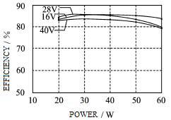
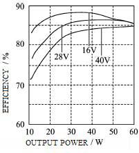
Figure 2 Efficiency (OUTPUT POWER) |
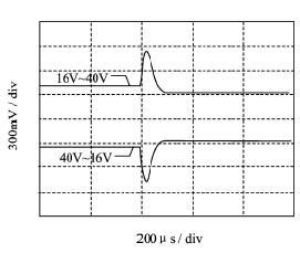
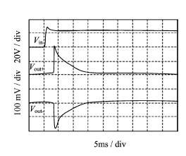
Figure 3 STEP LINE RESPONSE |
 |
 |
|
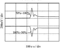
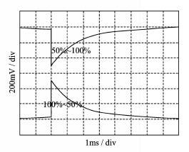
Figure 4 STEP LOAD RESPONSE |
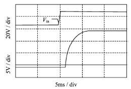
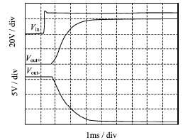
Figure 5 START-UP OVERSHOOT/ DELAY |
 |
 |
|
Figure 6 EFFICIENCY(OUTPUT POWER) |
Figure 7 STEP LINE RESPONSE |
 |
 |
|
Figure 8 STEP LOAD RESPONSE |
Figure 9 START-UP ERSHOOT/DELAY |

Subscribe to our weekly newsletter and receive exclusive offers on products you love!
 X
X


 Gold Supplier