|
Absolute Max. Rated value |
|
|
Output Voltage:46V Input voltage(Transient,50ms):8V,80V Output Power:145W Storage temperature:-65℃~150℃ |
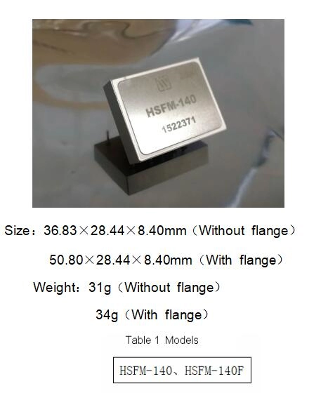
Mechanical Shock:1500g Lead resistance welding temperature:300℃(15s) Weight(Non-flanged/flanged):31g/34g Static strength:2000V |
|
No. |
Parameter |
Conditions (Unless otherwise specified,-55℃≤Tc≤125℃,VIN=28V±5%) |
HSFM-140 |
|
|
Min |
Max |
|||
|
1 |
Input voltage /V |
V0=V1-△Va,P0=140W(Pin 8) |
20 |
40 |
|
V0=V1-△Va,I0=7A(Pin 7) |
18 |
20 |
||
|
V0=V1-△Va,I0=6.5A(expect 18V)(Pin 8) |
16 |
18 |
||
|
2 |
Efficiency /%
|
TA=25℃,I0=5A(Pin 8) |
95 |
- |
|
3 |
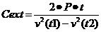
External storage capacitor ended output voltage/V |
V1=16V~40V,ICext=50MA(Pin 7),I0=0A(Pin 8) |
43 |
45 |
|
4 |
External storage capacitor ended output current/mA |
V1=16V~40V,Io=0A(Pin 8) |
- |
50 |
|
5 |
External storage capacitor terminal line regulation/V |
TA=25℃,V1=16V~40V, ICext=50MA(Pin 7),I0=0A(Pin 8) |
- |
250 |
|
6 |
External storage capacitor terminal current regulation /mV |
TA=25℃,V1=16V~40V, ICext=50MA(Pin 7),I0=0A(Pin 8) |
- |
250 |
|
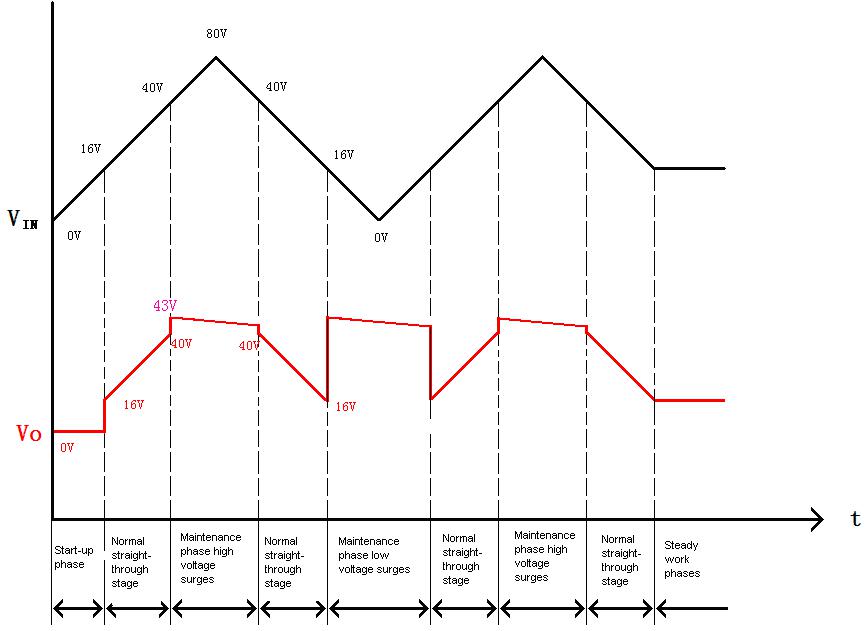
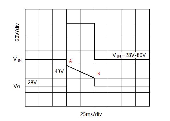
7 |
Input transientvoltage |
TA=25℃,Low input transient voltage duration time=50ms(Pin7 with 4700μF×Capacitor 3,Pin 8 with 140W constant power load) |
8 |
- |
|
TA=25℃,High input transient voltage duration time=50ms(Pin7 with 4700μF×Capacitor 3,Pin 8 with 140W constant power load) |
- |
80 |
||
|
8 |
Isolation |
TA=25℃,Any pin(except pin 6)connect 500V DC Voltage with package |
100 |
- |

|
Pin |
Symbol |
Designation |
|
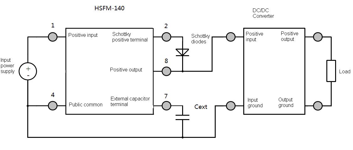
1 |
VIN |
Positive input |
|
2 |
Vd |
Schottky positive terminal |
|
3 |
NC |
null |
|
4 |
GND |
Input output common |
|
5 |
NC |
null |
|
6 |
GNDC |
Case common |
|
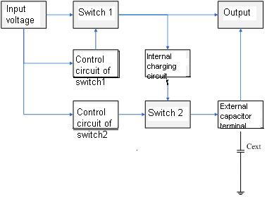
7 |
Cext |
external capacitor terminal |
|
8 |
VO |
Positive output |
 |
 |
|
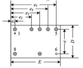
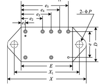
Figure 8 Bottom View |
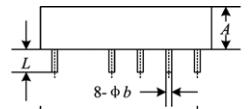
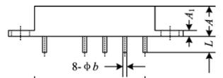
Figure 9 Side View |
 |
 |
|
Figure 10 Bottom View |
Figure 11 Side View |
|
Dimension Symbols |
Unit/mm |
||
|
Minimum |
Nominal |
Maximum |
|
|
A |
- |
8.4 |
8.90 |
|
A1 |
1.20 |
1.50 |
1.80 |
|
φb |
0.87 |
1.00 |
1.13 |
|
D |
- |
28.44 |
28.94 |
|
E |
- |
36.83 |
37.33 |
|
e |
- |
20.32 |
- |
|
e1 |
- |
5.21 |
- |
|
e2 |
- |
12.83 |
- |
|
- |
17.91 |
- |
|
|
e4 |
|
22.99 |
|
|
e5 |
- |
28.07 |
- |
|
X |
|
50.8 |
51.30 |
|
X1 |
43.45 |
43.95 |
44.45 |
|
P |
3.00 |
3.30 |
3.60 |
|
L |
5.35 |
6.35 |
- |
|
Case Model |
Header |
Header Plating |
Cover |
Cover Plating |
Pin |
Pin Plating |
Sealing Style |
Notes |
|
UPP3728-08c (Non-flanged) |
Cold Rolled Steel(10#) |
Ni |
Kovar (4J42) |
Ni |
Copper –coreCompound |
Ni/Au |
Compression Seal |
Nickel Plating is for case ground pin |
|
UPP3728-08d (Flanged) |
Cold Rolled Steel(10#) |
Ni |
Kovar (4J42) |
Ni |
Copper –coreCompound |
Ni/Au |
Compression Seal |
Nickel Plating is for case ground pin |

Subscribe to our weekly newsletter and receive exclusive offers on products you love!
 X
X


 Gold Supplier